Announcement

Collapse
No announcement yet.

Eric Dollard

Collapse
This is a sticky topic.
X
X
 
  • Filter
  • Time
  • Show
Clear All
new posts

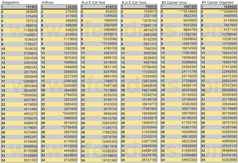
  • From a video titled "Rife Technology - A New Hope" that was once available on google videos but is no more:

    Rife's High Frequencies

    The following frequencies were found by Dr. Rife and used in his high frequency instruments. They were recorded on his lab notes. Some of these frequencies were used in Dr. Milbank Johnson's 1934 Cancer and Tuberculosis clinic. Many of these frequencies were only made public in the last few years.

    The only frequencies shown in this video were Rife's true high frequency M.O.R.s.

    All frequencies are listed in cycles per second.

    Actinomycosis (Streptothrix) - 192,000 - 678,000 - 186,554

    Anthrax - 139,000 - 900,000 - 272,539

    Anthrax Symptomatic - 400,000 - 16,655

    B. Coli (Rod form) - 417,000 - 683,000 - 317,914

    B. Coli (Filterable virus) - 770,000 - 8,581,000 - 11,103,424

    Bacillus X and Y (Cancer) - 1,604,000 - 11,780,000 - 17,033,662

    Bubonic Plague - 160,000 - 512,466

    Catarrh - 1,800,000 - 1,713,100

    Cholera Spirillum - 851,000 - 960,873

    Contagious Conjunctivitis - 1,206,000 - 2,025,625

    Diptheria - 800,000 - 1,090,154

    Glanders - 986,000 - 736,591

    Gonorrhea - 233,000 - 600,000 - 150,649

    Influenza (1918) - 1,674,000 - 1,946,704

    Leprosy - 743,000 - 251,926

    Pneumonia - 1,200,000 - 381,901

    Spinal Meningitis - 427,000 - 927,800 - 1,795,164

    Staphylococcus Pyogenes Aureus - 478,000 - 998,740 - 555,171

    Staphylococcus Pyogenes Albus - 549,070 - 549,070

    Streptococcus Pyogenes - 720,000 - 1,214,000 - 2,111,214

    Syphilis - 789,000 - 900,000 - 2,775,856

    Tentanus - 234,000 - 700,000 0 15,779

    Tuberculosis (Rod form) - 369,000 - 583,000 - 541,142

    Tuberculosis (Virus) - 770,000 - 8,518,000 - 11,103,424

    Typhoid Fever (Rod form) - 760,000 - 900,000 - 868,964

    Typhoid Fever (Filter passing) - 1,445,000 - 9,680,000 - 13,943,835

    -----

    Hoyland's Audio Frequencies

    The following audio frequencies were found by Philip Hoyland and used in the instrument he built for Dr. Rife. Rife didn't know the instrument was not using his high frequencies until the 1939 Beam Ray Corporation trial. These frequencies worked in Hoyland's instrument because of the unique way he built it. Hoyland's instrument worked on harmonics and produced Rife's high frequencies through harmonics. Dr. Rife did not like harmonics and did not approve of Hoyland's design.

    Hoyland's frequencies have been mistaken for Rife's frequencies. Though the doctors who used Hoyland's instruments reported very good results, the instruments would drift and not stay on frequency and many were returned. Hoyland's instruments did not work as well as Rife's high frequency instruments.

    All frequencies are listed in cycles per second.

    Actinomycosis (Streptothrix) - 7,870

    B. Coli (Rod form) - 8,020

    B. Coli (Filterable virus) - 17,220

    Bacillus X (Cancer - carcinoma) - 21,275

    Bacillus Y (Cancer - sarcoma) - 20,080

    Pneumonia - 7,660

    Staphylococcus Pyogenes Aureus - 7,270

    Streptococcus Pyogenes - 8,450

    Syphilis - 6,600

    Tentanus - 1,200

    Tuberculosis (Rod form) - 8,300

    Tuberculosis (Virus) - 16,000

    Typhoid Fever (Rod form) - 6,900

    Typhoid Fever (Filter passing) - 18,620

    Worms - 2,400

    -----

    Rife, Crane and Marsh 1950's Audio Frequencies

    The following audio frequencies were derived by dividing Hoyland's audio frequencies by a factor of ten.

    In the 1950's, Rife, Crane and Marsh became business partners. Rife had no schematics for his high frequency instruments. Hoyland built them but never gave a copy of the schematics to Rife. Rife did have an old Hoyland instrument. Rife, Crane and Marsh decided to re-design Hoyland's instrument and see how well it would work. They removed Hoyland's unique design of harmonics and gating. This made it so the instrument didn't produce any beneficial results. Instead of putting back Hoyland's method of producing harmonics they changed the sine wave audio frequencies to square wave to get harmonics. Then they lowered the audio frequencies by about 10 times.

    The doctors who used these 1950's instruments began to get very good results but after several years of testing they proved not to work as well as Hoyland's instrument. The changes to Hoyland's instrument were not good changes. Apparently Rife, Crane and Marsh never really understood how Hoyland's instrument worked. For years people have mistakenly believed these lowered audio frequencies were Dr. Rife's true M.O.R frequencies. Because of this confusion almost everything manufactured today is based on Hoyland's low audio frequencies and not Dr. Rife's high frequencies which achieved the results of Dr. Johnson's 1934 clinic.

    All frequencies are listed in cycles per second.

    Actinomycosis (Streptothrix) - 784

    B. Coli (Rod form) - 800

    B. Coli (Filterable virus) - 1552

    Bacillus X (Cancer - carcinoma) - 2128

    Bacillus Y (Cancer - sarcoma) - 2008

    Gonorrhea - 712

    Pneumonia - 776

    Staphylococcus Pyogenes Aureus - 727

    Streptococcus Pyogenes - 880

    Syphilis - 660

    Tentanus - 120

    Tuberculosis (Rod form) - 803

    Tuberculosis (Virus) - 1552

    Typhoid Fever (Rod form) - 712

    Typhoid Fever (Filter passing) - 1862
    Last edited by dR-Green; 02-16-2014, 08:59 PM.
    http://www.teslascientific.com/

    "Knowledge is cosmic. It does not evolve or unfold in man. Man unfolds to an awareness of it. He gradually discovers it." - Walter Russell

    "Once men died for Truth, but now Truth dies at the hands of men." - Manly P. Hall

    Comment


    • Originally posted by Goethe
      All things into one are woven, each in each doth act and dwell
      As cosmic forces, rising, falling, charging up this golden bell,
      With heaven-scented undulations, piercing Earth from power Sublime.
      Harmonious all and all resounding, fill they universe and time!
      Amidst life's tides in raging motion, I ebb and flood - waft to and fro!
      Birth and grave, eternal ocean, ever-moving, transient flow.
      A changing, vibrant animation, the very stuff of life is mine,
      Thus at the loom of time I sit and weave this living cloth divine.
      ..........
      http://www.teslascientific.com/

      "Knowledge is cosmic. It does not evolve or unfold in man. Man unfolds to an awareness of it. He gradually discovers it." - Walter Russell

      "Once men died for Truth, but now Truth dies at the hands of men." - Manly P. Hall

      Comment


      • Fischer Diathermy

        Tesla-Bcn,
        Having read your questions fully and note that this is early 1920s and before Vacuum Tubes (VT) were used, your questions are most difficult to answer.
        Much deeper research is required and this may help:

        The Turn Of The Century Electrotherapy Museum Tesla Library

        Could not find the video unit there and admit that my interest was in the use of VTs.
        You would really need to have a unit to copy as the engineering is superb and is simply not available today.
        The only thing I can suggest is to wade through the blueprints in the URL above and pull out what you require.

        Most impressed with the coils and capacitors as that is where we are at with the Tesla Magnifying Transmitter.
        Have been trying to buy a unit here but competition is fierce and postage/freight always a problem.
        People are after the simple technology that works - try doing solidstate with any of this!
        If I come up with anything new, will pass on,
        Sorry I can't help further.

        Smokey

        Comment


        • Originally posted by Sputins View Post
          @dr Green, you’re right, that is what the sting is, arcing to the fingers when the terminal is loosely held. I even received a slight burn through the insulation of the larger clamp, so the current can penetrate the insulation seeking a ground. Penetrate is the wrong term, it was if the current conducts through the (so called) insulation. One is better off to just to grab the metal. No problems. The larger the surface area of the held metal definitely helps. Yeah, less contact or varying the pressure of contact affects the brightness of the bulb. - Love the conventional dismissal comments, wires up the sleave of your woollen jumper hey? Lol.

          Now your amp is able to cleanly transmit music or signals which would be quite practical. Mine cannot as yet, but I might be able to modulate the key in some way to transmit some intelligence. (Morse code or other). Perhaps I can modulate the grid. The next push-pull transmitter will have (music) modulation as a feature.

          Light bulb lit, with the connection from coil to my hand seen.

          Now it’s time to go down to the local oval and look like a lunatic measuring out the wire for the extra coils..
          You underestimate their ignorance! They didn't think I had a wire up my sleeve, they thought my woollen sleeve was the conductor! The camera perspective made it look (to them) like I was touching one terminal with the bulb, and my sleeve was touching the other terminal so that was the obvious conductive path. Even though both terminals were in the same bucket of soil and there were no wires leading to the second terminal.


          Yeah when I was using HV and holding the insulation on a big clip the whole thing would light up purple under the insulation, potentially more dangerous than just holding the metal. What you describe as conducting through the insulation I think is capacitive coupling to your body, because the bulb will also light at lower voltages without any of the arcing. If you use a metal plate (experiment with size) then you should be able to vary the brightness depending on the distance of your hand from the plate.

          If you modulate your carrier signal input then it should work just the same as it does now but with some intelligence. Then it's just a matter of tweaking it to make the signal clean which might not necessarily be optimised for lighting bulbs, but it can be fun and distracting to overdrive it to try and get bulbs up to full brightness!

          Is it necessary to measure the wire? If you wind it on the frame then it should end up at the correct length anyway. Either way, I had the same dilemma of wanting to measure some wire so that's what the frame that's currently under my transmitter in the pictures was for. It was designed to have a circumference of 1 metre so 1 turn = 1 metre of wire. With a handle to turn it and a frame to hold it a mechanical counter can then be added to count the number of turns which corresponds directly to the wire length.
          http://www.teslascientific.com/

          "Knowledge is cosmic. It does not evolve or unfold in man. Man unfolds to an awareness of it. He gradually discovers it." - Walter Russell

          "Once men died for Truth, but now Truth dies at the hands of men." - Manly P. Hall

          Comment


          • If you take the below high frequencies from Rife and multiply them by 2 you get around the 3,2MHz. From what I read the 3,2 also resonates in the virus that resonates on 1,6 killing it.

            Influenza (1918) - 1,674,000
            Bacillus X and Y (Cancer) - 1,604,000

            Would it be a coincidence that my flu is healed in one day I wonder what others are experiencing with their coils? It is really beyond any reason the way I got cured from the flu. Never had that my whole life.

            Comment


            • If you take the below high frequencies from Rife and multiply them by 2 you get around the 3,2MHz. From what I read the 3,2 also resonates in the virus that resonates on 1,6 killing it.

              Influenza (1918) - 1,674,000
              Bacillus X and Y (Cancer) - 1,604,000

              Would it be a coincidence that my flu is healed in one day I wonder what others are experiencing with their coils? It is really beyond any reason the way I got cured from the flu. Never had that my whole life.

              When you look at these harmonics almost every virus resonates at 3,2MHz.


              Dr. Rife's True Original Frequencies

              Comment


              • Extracoils..

                Originally posted by dR-Green View Post
                You underestimate their ignorance! They didn't think I had a wire up my sleeve, they thought my woollen sleeve was the conductor! The camera perspective made it look (to them) like I was touching one terminal with the bulb, and my sleeve was touching the other terminal so that was the obvious conductive path. Even though both terminals were in the same bucket of soil and there were no wires leading to the second terminal.


                Yeah when I was using HV and holding the insulation on a big clip the whole thing would light up purple under the insulation, potentially more dangerous than just holding the metal. What you describe as conducting through the insulation I think is capacitive coupling to your body, because the bulb will also light at lower voltages without any of the arcing. If you use a metal plate (experiment with size) then you should be able to vary the brightness depending on the distance of your hand from the plate.

                If you modulate your carrier signal input then it should work just the same as it does now but with some intelligence. Then it's just a matter of tweaking it to make the signal clean which might not necessarily be optimised for lighting bulbs, but it can be fun and distracting to overdrive it to try and get bulbs up to full brightness!

                Is it necessary to measure the wire? If you wind it on the frame then it should end up at the correct length anyway. Either way, I had the same dilemma of wanting to measure some wire so that's what the frame that's currently under my transmitter in the pictures was for. It was designed to have a circumference of 1 metre so 1 turn = 1 metre of wire. With a handle to turn it and a frame to hold it a mechanical counter can then be added to count the number of turns which corresponds directly to the wire length.
                Maybe you had metal fibres woven into your jumper? - Like steel wool, that must be it! We're on to you now, lol.

                After measuring out the wire, (66.2 meters) I constructed the first version Extracoil following the ‘Tentative Extracoil’ calculation formula. I found that for my spiral coil the extra coil inductance was too large, and the frequency of it too low to resonate compared to that of the spiral coil (and adding any capacitance will bring it down even further). Unwinding it some then made the length to height ratio incorrect. - I noticed that this maybe why you recently added the variable air capacitor across the secondary coil on your rig, as to bring down the secondary frequency to match the Extracoil’ s frequency better?

                Yeah, I would agree that measuring out the wire may be unnecessary. I do it because then I can measure out two identical wire lengths, (side by side), then I know for sure they are both the same length and it’s a physical measurement conformation to the calculated length by the number of turns method.

                Having said that, I unwound the Extracoil and started again, this time using a larger diameter wire and larger space (length by calculation this time). Amazingly, this time the self-resonant frequency of the (new) extra coil is almost exactly the same as the spiral coil self resonant frequency. 2.08Mc V 2.085Mc, however the Extracoil is over 57% longer in wire length with a 1:1 H x L ratio. So I’m happy to work with that for now, as I’ll be trying for a capacitive coupling link between them, not directly connected as Eric highlights.

                As for lighting bulbs: I have bought some ‘vintage style bulbs’, not really vintage, but copies of, which are 25W bulbs but they have long fine filaments and a large vacuum space. All of these bulbs light quite nicely. The small 25watt bulb shown in my previous picture, when I push my amp to full power, the light from that bulb is something to behold, it is @#$! blinding! Extremely bright.

                I’ll have to give the plate and hand trick a go too, which sounds like some fun. - I’ll continue to play with adding the extra coil to my rig and see what happens with that.

                Pictures of the ‘vintage’ bulbs, Extracoil, with some statistics and results to come later.

                Sputins.
                "Doesn't matter how many times you kick the coyote in the head, it's still gonna eat chickens". - EPD

                Comment


                • Rife Machine

                  On The Rife Machine Report, A History of Rife's there is a book on Rife that tells the truth to what Rife had. Three real Rife Machine were found and were reverse engineered and documented. It is stated in the book the TRUTH to the method. However, it is used to promote equipment that is NOT applying the method in the book!

                  This is the book I'm taking about: The Rife Machine Report, A History of Rife's Instruments and Frequencies

                  I hope to be able to share more soon but that's all I can go into right now.

                  Just fyi for anyone interested.
                  Last edited by Aaron; 02-17-2014, 02:00 AM.
                  Sincerely,
                  Aaron Murakami

                  Books & Videos https://emediapress.com
                  Conference http://energyscienceconference.com
                  RPX & MWO http://vril.io

                  Comment


                  • Originally posted by Sputins View Post
                    After measuring out the wire, (66.2 meters) I constructed the first version Extracoil following the ‘Tentative Extracoil’ calculation formula. I found that for my spiral coil the extra coil inductance was too large, and the frequency of it too low to resonate compared to that of the spiral coil (and adding any capacitance will bring it down even further). Unwinding it some then made the length to height ratio incorrect. - I noticed that this maybe why you recently added the variable air capacitor across the secondary coil on your rig, as to bring down the secondary frequency to match the Extracoil’ s frequency better?
                    Can't you space the turns out to get the height to diameter ratio back up?

                    I'm directly scaling down Tesla's Colorado Springs coil so that doesn't use any of the CRI calculations given by Eric. In this case I know what the scaled frequencies should be, but my measured secondary frequency is slightly higher because of the burdening or stray/parasitic components on Tesla's coil that isn't present in mine, so I added the air condenser to get the frequency back down to the proper scaled (design) value. The priority here is to maintain the same wavelengths, LC ratios, impedance etc between the coils as the full scale version in order for the scale model to work/do the same thing. Hopefully I get delivery of materials tomorrow and I can start with the extra coil tuning. I plan to test the secondary with Eric's extra coil design or a variation thereof at some point, since we already know that the extra coil frequency is low, but no one knows what the optimal relationships are in Eric's design so that's entirely experimental.
                    Last edited by dR-Green; 02-17-2014, 02:42 AM.
                    http://www.teslascientific.com/

                    "Knowledge is cosmic. It does not evolve or unfold in man. Man unfolds to an awareness of it. He gradually discovers it." - Walter Russell

                    "Once men died for Truth, but now Truth dies at the hands of men." - Manly P. Hall

                    Comment


                    • Originally posted by dR-Green View Post
                      Can't you space the turns out to get the height to diameter ratio back up?

                      I'm directly scaling down Tesla's Colorado Springs coil so that doesn't use any of the CRI calculations given by Eric. In this case I know what the scaled frequencies should be, but my measured secondary frequency is slightly higher because of the burdening or stray/parasitic components on Tesla's coil that isn't present in mine, so I added the air condenser to get the frequency back down to the proper scaled (design) value. The priority here is to maintain the same wavelengths, LC ratios, impedance etc between the coils as the full scale version in order for the scale model to work/do the same thing. Hopefully I get delivery of materials tomorrow and I can start with the extra coil tuning. I plan to test the secondary with Eric's extra coil design or a variation thereof at some point, since we already know that the extra coil frequency is low, but no one knows what the optimal relationships are in Eric's design so that's entirely experimental.
                      I suppose I could’ve spaced the turns out to get the diameter ratio back up, but I figured it was easier to unwind it (plus keeping my 66.2 meter wire for later, rather than cutting it) and also achieve a more accurate result to just re-wind it.

                      Okay that explains what you’re doing there exactly. You’re building a scale model of the CS coil. I suppose since you’re scaling down the size of the coil, the scale frequency goes up accordingly. As you say, it would be the LC ratios, coil shape & impedances that would be most important etc. I think (as you would already know) Tesla says that 30Kc or below worked best for telluric propagation, but that’s for a full size 50-something-foot coil. What is your generalised scaled down ratio?

                      My current rig design is loosely based on Eric’s but it’s all experimental for sure.
                      "Doesn't matter how many times you kick the coyote in the head, it's still gonna eat chickens". - EPD

                      Comment


                      • Rife

                        That's a fascinating website about Rife's machine Aaron.

                        Does anyone else see a comb generator in all the spectrum plots?

                        After reading a good portion of what that site had to offer, I don't think it's about any one "special" frequency, more a discreet interval of amplitudes and evenly spaced harmonics. Theory of comb generators would do anyone looking into this subject a world of good, that and a solid understanding of time and frequency domain concepts.

                        Also, the sharp rise time shown for the time-domain signal is very interesting. As anecdotal evidence toward harm to the human body, I've dealt with high slew rate dV/dt signals and have gotten headaches and gray hairs! This on multiple occasions, and I'm not at that age which garners gray hair for free. Which, should let people realize that it's not "all good." Care and thoughtfulness is paramount if working with these type of experiments.

                        Comment


                        • Regarding frequencies that are precursors to earthquakes.

                          Some think that earthworms and toads become irritated before earthquakes, Not liking this event they come to the surface. Toads in large numbers begin moving away.

                          By setting sensors on earth worm activity on an earth plot having a large cylindrical coil on top it might be possible to find such a frequency or a product of this mysterious precursor.

                          The visual effects seen with clouds brings me to speculate that the earth emits waves of some sort forming a belt, an emission event near epic centers.
                          What some have seen before earthquakes may be the light diffracted by this belt against the backdrop of a cloud.
                          Unlike a rainbow the light formation is localized, can be distinguished by the scratchy vertical lines or striations.

                          Last edited by mikrovolt; 02-17-2014, 01:54 PM.

                          Comment


                          • Originally posted by Aaron View Post
                            On The Rife Machine Report, A History of Rife's there is a book on Rife that tells the truth to what Rife had. Three real Rife Machine were found and were reverse engineered and documented. It is stated in the book the TRUTH to the method. However, it is used to promote equipment that is NOT applying the method in the book!

                            This is the book I'm taking about: The Rife Machine Report, A History of Rife's Instruments and Frequencies

                            I hope to be able to share more soon but that's all I can go into right now.

                            Just fyi for anyone interested.
                            Thanks. From reading the webpage I think we can compare our frequencies with multiplies of the frequencies Rife used. I might have stumbled on a useful one but other frequencies might overlap too with a lot of them. Perhaps a little tuning with a condenser might be fruitful here.
                            The instrument Rife used was totally different I think Vassilatos says it is a tube working electrostatic because gas lamps did not work at all in all colours. Read Vassilatos 'lost science' on that.
                            But in all Vassilatos work he did not understand that Tesla did not just use high voltages or pulses to separate aether from electrons. This tuning by Dollard is just as effective and much simpler. Combined with high voltages like you guys allready have it must get even better But for cancer we must also tune to the right frequency it seems now.

                            Comment


                            • Multiple frequency spectrum

                              Hi orgonaut314:

                              It is interesting to note that the Lakhowsky Multiple Wave Oscillator (MWO) had a very broad frequency spectrum covering possibly all the frequencies used by Dr. Rife.
                              I have built two of the MWOs one with Erick's log periodic antenna and the other with Dr. Bob Beck designed antenna. I got much more action out of Bob Beck's design. First I built one based on Peter A. Lindemann's "The Final Approach", slightly modified, running on a 12 V car battery. Then I built the original Bob Beck design using the T Ford ignition coil and a 6 Volt battery. It works much better than the first one, even thought I need a more precise adjustable spark gap. If someone needs more info, please let me know.

                              Comment


                              • Deeplu Thank You

                                Originally posted by David G Dawson View Post
                                Tesla-Bcn,
                                Having read your questions fully and note that this is early 1920s and before Vacuum Tubes (VT) were used, your questions are most difficult to answer.
                                Much deeper research is required and this may help:

                                The Turn Of The Century Electrotherapy Museum Tesla Library

                                Could not find the video unit there and admit that my interest was in the use of VTs.
                                You would really need to have a unit to copy as the engineering is superb and is simply not available today.
                                The only thing I can suggest is to wade through the blueprints in the URL above and pull out what you require.

                                Most impressed with the coils and capacitors as that is where we are at with the Tesla Magnifying Transmitter.
                                Have been trying to buy a unit here but competition is fierce and postage/freight always a problem.
                                People are after the simple technology that works - try doing solidstate with any of this!
                                If I come up with anything new, will pass on,
                                Sorry I can't help further.

                                Smokey
                                Thanks David.

                                I will write to them directly and see what they say. In Spain in a town named Terrassa closer to my home, there is a museum of ancient technology; it is probably that they still keep an ancient french's Diathermy Machine.

                                I already see that this will not be easy.

                                Anyway, I think my hypothesis that the planes transformers made ​​with copper foil must have a high self-capacitance is important to keep in mind. I will let you know of my progress soon. If anyone know a way to calculate the resonance of stripped laminar bifilar copper coil, that will be very useful as well. I think that that algebra, was lost again in some place.

                                In the meantime, thanks again.

                                Comment

                                Working...
                                X