Announcement

Collapse
No announcement yet.

Eric P. Dollard

Collapse
This topic is closed.
X
This is a sticky topic.
X
X
 
  • Filter
  • Time
  • Show
Clear All
new posts

  • 60 KV Transformer, Final

    (1) Given in the previous transmissions is that there exists three distinct modes in which this transformer can operate.

    I) As a power transformer for machine frequencies. The inductance is space scalar and the dielectric energy content is negligible.

    II) As a resonant transformer for VLF frequencies. The inductance is a sine function of space and a considerable quantity of dielectric energy content exists, equal to the magnetic energy content. The capacitance is now a cosine function of distance. This resonant energy exchange is powered by a loose coupled source of Alternating Current through the primary winding.

    III) As an extra coil for VLF frequencies. Again equal energies in a resonant exchange but now series fed through the neutral to earth connection. The primary coil now is inactive in this operation.

    2) Some further experiments are in order here.

    The DC, or static, resistance of the 60 KV secondary winding is measured to be:
    24 Ohm

    Handy is a car battery:
    12 Volt

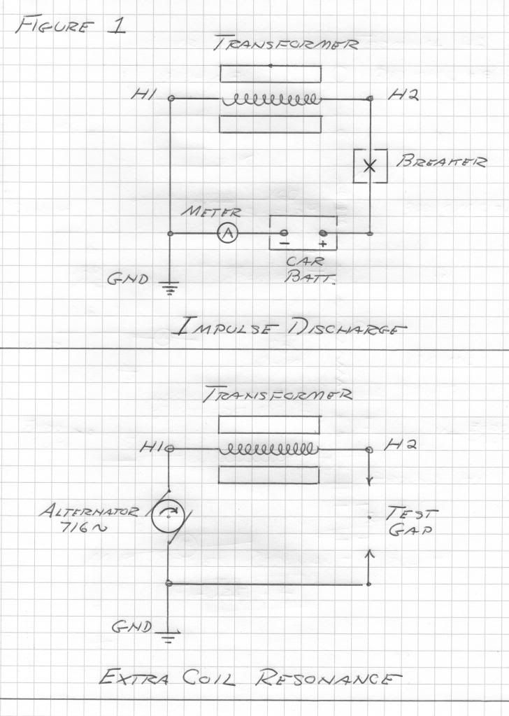
    Now connecting the line, H2, terminal to its line vacuum breaker, Figure 1, and connecting the line side of the breaker to the positive terminal of the car battery, a basic current loop is formed.

    The negative terminal of the car battery is connected to an ammeter and then to the transformer neutral. The neutral, H1, is grounded to station ground.

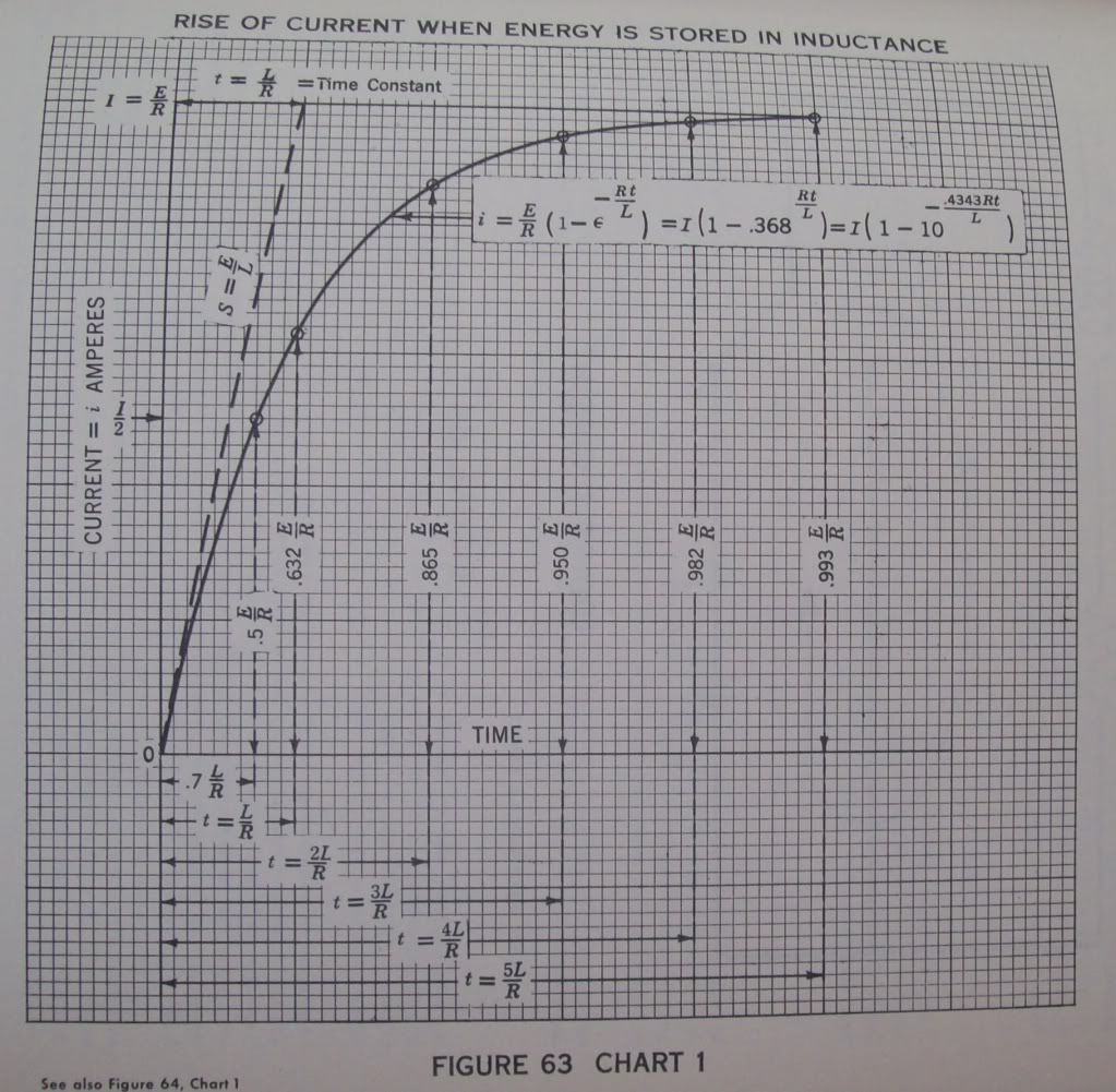
    3) The vacuum breaker is closed completing the current loop, this loop a basic, L,R, circuit of 24 Ohm and 160 Henry. Upon closure a stopwatch counts time from the instant of this closure, T, equals zero. Observing the ammeter it is seen to rise very slowly. At the point when the ammeter reads
    316 milliAmpere

    The stopwatch is checked. The span of time to reach 63.2 percent of the maximum value is called the magnetic time constant, u. The stopwatch reads
    6.7 seconds

    The ammeter continues to climb, in ever smaller increments closer and closer to 500 milliAmp. It is noticed it takes over 33 seconds for the inductance to reach full charge. See figure 63.

    At full charge the winding current is one half Ampere. The static winding inductance is 160 Henry. Hence the magnetic energy storage is derived as
    20 Watt-second

    4) Now the vacuum breaker is tripped, this instantaneously breaking the loop. A streamer several feet long erupts from the line, H2, bushing insto space. Since no escape of energy exists the magnetic energy is abruptly converted into dielectric energy at a fundamental frequency and its odd order harmonics. This was given as
    716 cycles per second

    The effective values of inductance and capacitance were determined to be 100 Henry
    and
    500 picoFarad

    By the law of conservation of energy the magnetic energy equals the dielectric energy. By algebraic operation the ratio of EMF to current is the square root of the ratio of 100 Henry and 500 picoFarad,
    450 Kilo_ohm

    And thus from a 12 Volt car battery the EMF developed at the line terminal, H2, is derived as
    225 KiloVolts peak

    This assuming a sinusoidal waveform. Here the harmonics were burned off in the streamer issuing from H2.

    (5) The increase in frequency from 60 cycle to 716 cycle gives an increase of the effective resistance to 72 Ohm, at 716 cycles per second. The effective inductance is 100 Henry. The reactance of this inductance at the oscillating frequency, Omega,
    4500 radians per second

    is derived to be Omega L or
    450 Kilo-Ohm

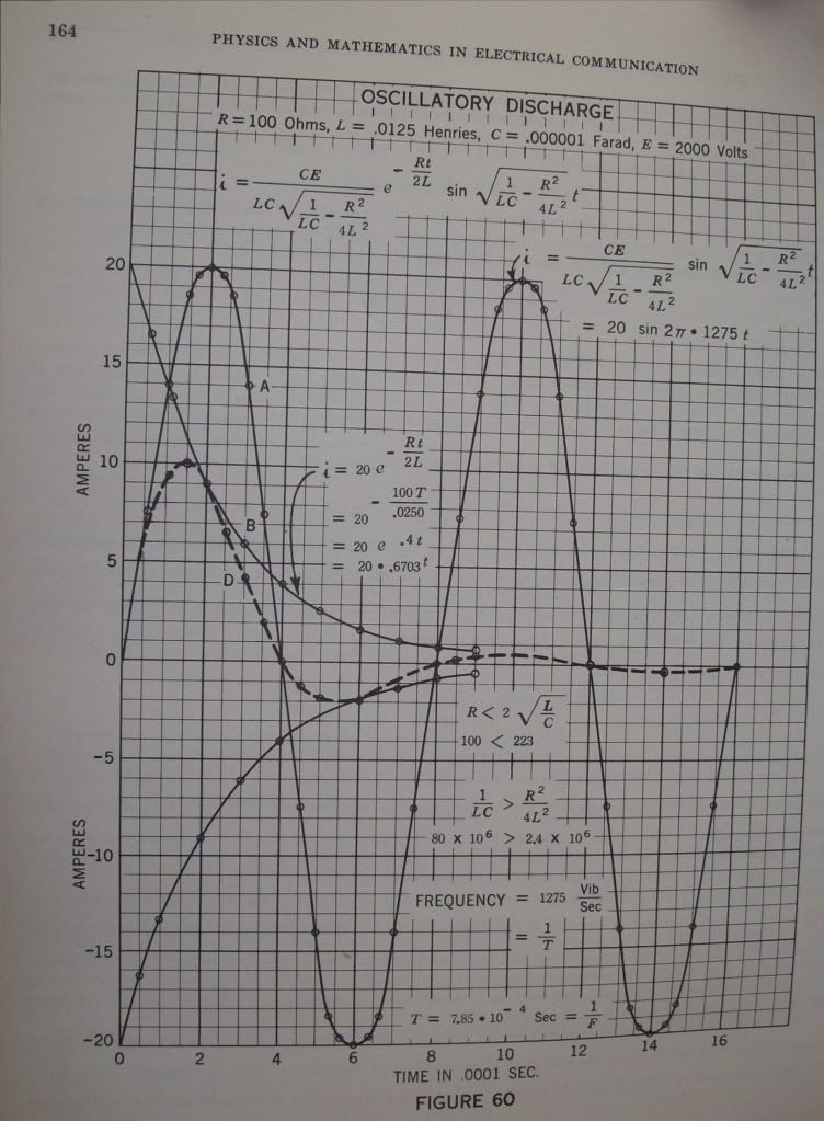
    And the time constant of the 716 cycle oscillation is derived from the effective inductance in proportion to the effective resistance, L, over, R. It is however that the oscillatory energy is magnetic only half the time, the other half is dielectric. Hence the time constant is given as one half the ration of inductance to resistance, one half of
    1.39

    Gives the oscillatory time constant as,
    .7 seconds

    At this time the magnitude of the oscillation has diminished to one over Epsilon, or
    36.8 percent

    The oscillation becomes inaudible in about five times this, or,
    3.5 seconds

    See figure 60.

    (6) The magnification factor of this oscillating winding is determined by the ratio of the effective winding reactance to the effective winding resistance,
    450 Kilo-Ohm
    to
    72 Ohm
    Giving
    6250 numeric

    The initial, or peak, current is one half an ampere this the effective value, or per square root of two, is given,
    356 milliAmpere RMS

    The initial, or peak, EMF is given as 225 Kilo-Volt, hence the effective value is,
    159 Kilo-Volt, RMS

    The product of these values gives the total oscillatory activity in the transformer winding,
    56.6 Kilo-Volt-Ampere

    (7) The losses in the windings are given by the square of the effective current times the effective resistance, I squared R, or the Back EMF developed by the losses is the current times the resistance, I, times, R, or

    25.6 Volt

    Here from are derived the basic transformation parameters in the operation of the 60 KV secondary winding as a resonant extra coil, this for an output potential of 160 KV at 716 cycles per second.

    Input (H1) Power Requirement
    9.1 Watt

    Input Impedance, E, over, I, or,
    72 Ohm

    This a resistive load as seen by the source of alternating electric energy. Hence, a 10 watt audio amplifier, on the 50 Ohm output tap, will give rise to a resonant oscillation, building up over a time span of 3.5 seconds, this with an activity of 56.6 KiloVars and an electrostatic potential of 160 KiloVolts. Here established is the concept, -- "Magnification Transformer"

    73 DE N6KPH


    From Perrine's book "Physics and Mathematics in Electrical Communications":

    Last edited by t-rex; 07-01-2012, 01:06 AM.
    SUPPORT ERIC DOLLARD'S WORK AT EPD LABORATORIES, INC.

    Purchase Eric Dollard's Books & Videos: Eric Dollard Books & Videos
    Donate by Paypal: Donate to EPD Laboratories

    Comment


    • The best work of Eric Dollard & How it may relate to Edward Leedskalnin

      Eric,

      This is some of the most fantastically presented descriptions of the magneto dielectrics that I have ever had the joy of seeing. Thank you. I wanted to ask you a question, do you know what happened to the original Maxwell I's before they were diluted by Heaviside? Me and some friends are really struggling to get hold of them. It's important to me because I'm writing a book called "Technology for a New Future" trying to desperately document everything that happened since the days of R.C.A

      I have read a very good book that has what I consider to be identical explanations for many of the aforementioned effects by Dollard. I have mentioned before, Magnetic Current by Edward Leedskalnin on this thread. Eric, others, please give it a chance. Some snippets from the book will reveal why it is an important thing. Often engineers, such as scientists will refer to the "fields" being responsible for creating or synthesising this theoretically magneto dielectric interaction. However I believe the term energy from the air running in crosswise faster than the coil propagates lengthwise is a substantially clearer argument for even the most wooden headed of scientists!

      Leedskalnin at length appears to discuss the differences between the dielectric and the magnetic kind of current. I believe Eric has said many times that "electrons" are radiation resistance by definition. E.g. Electrons do not exist as the smallest particle of current; or otherwise electrons would not be a secondary effect. They are a secondary effect, I will explain why.

      In substitution of regular engineering words Leedskalnin uses "cross wise" & "Lengthwise" flow of currents as a basis for running current in transformer coil windings. I believe that this simplification is both relevant & astonishing. It matches up with Eric's work perfectly. Perfectly. Here is an extract I believe will be helpful to both amateurs and professionals alike. This work was done in 1945. A long time ago, not long after WW2 & R.C.A. What really got my attention last night whilst reading was the repeated term "Bulk form". It is interesting, Leedskalnin and Dollard both speak about it, they both seem to underline how it is important in the creation of a dielectric, magneto dielectric system. It appears to me that depending on the ratio of crosswise to lengthwise running current is the manifestation or suppression of the propogation speeds between them. Leedskalnin gives a truly wonderful explanation.

      "Now you see those little individual magnets ran out of the U shape magnet and ran in the soft iron core, but the soft iron core never held the magnets, it pushed them out. To prove it you put five or si thin iron strips on edge, slant just so they will not flop over, now approach to the ends of those strips with a magnet and you will see they flop over, hold the strips a little loose by the ends, then they will spread out. I think this is enough to show that the soft iron never held those magnets. It pushed them out. As soon as those little individual magnets get pushed out of the soft iron core of the transformer then they run in the coil. When they run in the coil they are in bulk form. The coil's part is to divide those little individual magnets from bulk form in small paths. The coil is not necessary to make magnetic currents. Currents can be made with a single wire. The coil is necessary to increase the amount and strength of the currents. The coil is similar to any cell battery. One cell alone does not amount to anything. To be good many cells have to be in a battery. The same in a coil to be good many turns have to be in a coil." - Edward Leedskalnin on the properties of Iron & Alternative Description of Current flow that is ultimately compatible with Magneto Dielectric theory and 4 Quadrant theory of Eric Dollard.

      "When the magnets that are in bulk form enter the coil then the coil divides them in small paths. It is done in this way. When the bulk magnets enter the coil they fill the coil's wire with North and South Pole individual magnets. North pole magnets pointing towards South pole U shape magnet and South Pole point towards north pole U shape magnet. Now the wire in the coil is one concintuous magnet. One side of the wire is South Pole and the other North Pole (area of circle/2). Now we have those little North and South pole individual magnets in the wire, but they are not running in the way we want. They are running across the wire. We want the magnetic current to run through the wire lengthwise, but there is only one way to do it, we have to increase the number of those North and South Pole individual magnets. (Voltage?). To do it the coil will have to approach and enter the U shape magnet, but when the coil reaches the middle of the U shape magnet there is a limit so the running of the currents stop. In the core and the coil there is plenty of those little magnets, but they stopped to run through the wire lengthwise, now they run only accross the coils wire, to make the magnets run in the wire lengthwise again the coil will have to get away from the U shape magnet. As soon as the coil begins to move away from the U shape magnet, then those little North and South pole individual magnets begin to run again through the wire lengthwise, but in opposite direction until the magnets in the iron core are gone." - Edward Leedskalnin discussing the 90 degree difference between a 0 degree longitudinal wave form and a 90 degree transverse wave propagation, and basic concept of Alternating Current theory. (Also the difference between magnetism and di-electricity is discussed here briefly).

      Edward Leedskalnin then provides an experiment which tells how to get a current to run crosswise and lengthways. It is a basic experiment.

      "Wrap six inch long soft iron wire with paper insulator, put the wire in box in iron filings, now put the box between a U shape magnet prongs. Raise the wire up then you will see filing strands clinging to the insulated iron wire. Raise the wire up slowly, then the filing strands will sag and fall, take the box out, put the wire in the filings again, raise up and you will see that the wire is no magnet, but during the time it was between the U shape magnet prongs it was a magnet. [ this is akin to the effect between the primary and secondary and the secondary and extra coil, this is why no other metal conductors or insulators can be nearby without impeding the device's function. ]. This shows that during the time the coil moves through the U shape magnet, the coil becomes a magnet, but it's function is double. Some individual North and South Pole magnets run throughthe coil's wire crosswise, and some run through the coil's wire lengthwise" - Edward Leedskalnin, a test for detecting a crosswise and lengthwise current, and understanding the difference between the dielectric and magnetic component, and their 90 degree relationship.

      "You saw how the magnets are running through a wire cross-wise. Now I will tell you how they are running through the wire lengthwise. Before the magnets start to run through the wire lengthwise they are lined up in a square across the wire, one side of the wire is North pole magnet side and the other side is South pole Magnet side [(circles area / 2 ) renders the pole divisions IN ALL TRANSFORMERS in tandem or otherwise?]. When the coil begins to approach the middle of the U shape magnet and the currents begin to run then the magnets which are in the wire begin to slant, North Pole magnets pointing East the same as the coils wire end, where the North pole magnet current came out and South Pole magnets pointing West the same as the coils wire end where the South pole magnets came out. When the coil reaches the middle of the U shape magnet then the currents stop to run. Now the North and South Pole magnets are pointing accross the wire again. When the coil begins to move away from the middle of the U shape magnet and the currents begin to run then the magnets which are in the wire begin to slant, but this time the North pole magnets are pointing West the same as the coil's wire end where the North pole magnet current came out and south pole magnets pointing east the same as the coils wire end where the south pole magnet current came out. When the coil moves out of the U shape magnet's effective distance the currents running stop. This is the way the alternating currents are made. - Edward Leedskalnin discussing the geometrical lay of the land being a factor in the running electrical generators. As Eric Dollard has pointed out Marconi was very wise in how he placed his facility. It was done in the "old way". Not just respecting the geographical poles, but the "true ones" too.

      "When the individual North and South pole magnets are running through a wire lengthwise they are running in slant and whirling around while running ahead. You can see the slant by watching the sparks when you are putting together and pulling away soft iron wire ends which are connected to the battery by their other ends. To see how the currents are running out of the coils wire watch those six one inch long magnets which lie on the glass." - A small confirmation from Edward Leedskalnin that he certainly is talking about dielectric materials and their electrostatic behaviour with transformer windings. Or rather, magnetic currents as he insisted on putting it. Put those magnets together with ends even, then let them loose, then you will see that they will roll away and if the magnets be stronger then they will roll away farther. This is the way the North and South pole individual magnets are running out of the coils wire lengthwise.

      The reason the North and South pole individual magnets do not run across through the coils wire as fast out as they run in while the coil is between the U shape magnet, is because the coils wire is insulated, there is an air space around every wire and as it is known that the dry air is the best obstruction for the magnets to go through and as you know the coil is well insulated so the damp air does not get in . IT is well known that it is many times easier for the magnets to run in metal than in air, now you see when the magnets run in the wire they hesitate to run out of the wire across the same way as they came in, so more of the new magnets are coming in the wire CROSSWISE, then they can get out CROSSWISE, so they get pushed out through the wire lengthwise. Now you know how Alternating Currents are made". - Edward Leedskalnin declaring that the crosswise current creates alternating current & explaining why their is a speed difference in the currents running through (he goes on to explain it much better).

      Here is my favourite bit:

      "You have been wondering why alternating currents can run so far away from their generators. One reason is between every time the currents start and stop there is no pressure in the wire so the magnets from the air run in the wire and when the run starts again there are already magnets in the wire which do not have to come from the generator, so the power line itself is a small generator which assists the big generator to furnish the magnets for the currents to run with. [ In short Leedskalnin has described than an advanced transmission line condition exists which allows power lines to gain crosswise magnetic field energy by running the fictional electrons lengthwise, which as Ed establishes are 2 pole alternation).

      (continued below)

      Comment


      • The best work of Eric Dollard & Leedskalnin, 2 planes (II)

        (continued from above)


        Edward Leedskalnin finishes it all up with the grand statement "I have a generator that generates currents on a small scale from the air without using any magnets around it."

        My belief is that so did Tesla. So has Eric. Am I right Eric? Is this the illusive synthesis of electrical current that has been discussed before now? I believe it to be so.

        "ANother thing you have been wondering how a U shape permanent magnet can keep it's magnet strength indefinitely. You know the soft iron does not hold magnets, but you already have a U magnet that holds it. It is the perpetual motion holder. It illustrates the principle how permanent magnets are made. All that has to be done is to start the magnets to run in an orbit, then they will never stop. Hard steel U shape magnets have a broken orbit, but under proper conditions it is permanent. I think the structure of the metal is the answer. I have two U shape magnets. They look alike, but one is a little harder than the other. The hader one can lift three pounds more than the softer one. I have been tempering the other steel magnets and have noticed that the harder the steel gets the smaller it becomes. That shows that the metal is more packed and has less holes in it so the magnets cannot pass through it in full speed, so they dam up in the prong ends. They come in faster than they can get out. I think the ability for the soft steel welding rod to hold magnets is in the metals fine structure.

        Leedskalnin summarises his view and justifies it's position "The reason I call the results of North and South pole magnets functions magnetic current and not electric currents or electricity is the electricity is connected (by engineering and science) too much with those non-existing electrons. If it had been called magneticity then I would accept it. Magneticity would indicate that it has a magnetic base and so it would be all right.

        It seems at the very least, E.D.L in 1945 felt similary to Eric Dollard and Tesla. Remember Tesla described the work of electrical engineers and scientists as "Works of fiction". Perhaps we can see why, because on the most very basic levels the understanding of magnetism being a static field entirely seperate from the dielectric is a DOGS MESS!! Eric and Ed's work seems to prove that.

        It is why I had to share it! Eric went to a great deal of time sharing his view. So did Leedskalnin. I just want to make sure it gets heard.

        Today it is too important. Notice that Dollard and Leedskalnin both claim it is possible to make electricity (please correct me if I am wrong Eric) from the surrounding aether, via an theoretical energetic synthesis between crosswise currents and lengthwise currents. I hope it becomes readily apparent that these 2 planes combined create the 4 quadrants Eric has spoken of fondly. Also they are exactly 90 degree's apart at all stages in the period radial of a circle. Therefore the crosswise and lengthwise terms form more than a coincidental factor in the difference between a 1 plane 0 degree longitudinal magneto dielectric "telluric" type emination and a 90 degree transverse space/time 2 plane wave. It appears as if one is "Newtonian". whereas the other one isn't. As Eric has repeatedly said over and over again, this is because the crosswise dimension of the longitudinal wave is exactly 0.

        I believe the longitudinal wave widens upon contact with a conductor, but essentially it is virtual, non existent particle relationship with poles which has more in common with Quantum Physics than Newtonian law.

        I appreciate this may be a distraction, but it is too goddamn important to stay quiet about! I help my assistance and commentary make Eric's and Leedskalnins work easier to understand, there can be no greater amateur than me. However if I was not a musician I would not have realised the critical difference between a vertical and a horizontal shift.

        Wishing you all the greatest successes in creating your Magnetic Flywheels and Parametric Transformers which are self-referencing and non-limited by a secondary current plane that suppresses it. All your angles must be perfect as far as I can see in my lab, e.g. my bedroom.

        Just imagine what kind of research could be done if people helped fund Eric. Just imagine. I hope this post also creates some understanding about how a theoretical concatenated mode of coil operation might work in the same multiplicative stages of a tandem coil by a more indirect root of dividing the primordial waves just on a different order of resonance harmonic standing-wave relationships. "Queued Paths"? As a metaphor only. What I am suggesting is that the longitudinal and transverse waves exist in all conductors that propogate. There are essentially 2 methods layed out for magnification factors, adapting the field by division and recombination (concatenated) and adapting the field by multiplication as a recombination. Essentially though I'm out of my level of experience now. So I will pass it back over to Eric, Dr-Green, Dawson and others.

        I do hope you are able to make further work on this, or I might have to start recreating the T.M.T and Multiple Loaded Flat Top Antennae' myself. It is my hope that humanity can undertake this important achievement. The greatest since the discovery of fire. It will take great men who's greatest care is of humanity, and not greed to make this technology a living , breathing, reality.

        All my puns are quite intended.


        Eric, and others, I want to ask you what you think the fabric of electricity consists of, or the so-called particles. Are these fields, or individual magnets? Or electrons? These 3 choices seem to exist at all stages in electricity. If Dollard is right as I feel Leedskalnin and my electrical experiments with leverage and balance seem to show me, then the electron doesn't exist whatsoever. IF the electron doesn't exist? We need to throw the last 100 years of science into the trash man at 1.54C urgently. Else face the Heaviside effect as responsible and educated men; and that sort of frustration anger and contempt, I think we would all be best to avoid - especially given the importance of holding on with both hands to the engineering that Eric has blessed our world with, might I add out of charity and hope. Perhaps one day, when this is no longer suppressed and educated men are able to work on it, we will be able to abandon hope not through inferior ability, but through superior understanding.


        Best Wishes,
        Adam
        Last edited by 7redorbs; 07-01-2012, 04:06 PM.

        Comment


        • Originally posted by 7redorbs View Post
          I do hope you are able to make further work on this, or I might have to start recreating the T.M.T and Multiple Loaded Flat Top Antennae' myself. It is my hope that humanity can undertake this important achievement.
          "If not you, then who? If not now, then when?"

          http://www.teslascientific.com/

          "Knowledge is cosmic. It does not evolve or unfold in man. Man unfolds to an awareness of it. He gradually discovers it." - Walter Russell

          "Once men died for Truth, but now Truth dies at the hands of men." - Manly P. Hall

          Comment


          • So far with the new extra coil it has been found that to get resonance at 3670 kc the condenser rings need to be set at maximum capacitance, and equally maximum relative terminal capacitance on the extra coil. The extra coil as tested standalone with a metallic connection needs LESS terminal capacitance to be resonant at 3670 kc as compared to being in series with the secondary.
            http://www.teslascientific.com/

            "Knowledge is cosmic. It does not evolve or unfold in man. Man unfolds to an awareness of it. He gradually discovers it." - Walter Russell

            "Once men died for Truth, but now Truth dies at the hands of men." - Manly P. Hall

            Comment


            • As usual, A, brilliant. We haunt the same places on the web, it seems.

              EDIT to add: Added My piece, The End of Entropy, here, too: http://www.energeticforum.com/renewa...d-entropy.html

              Since Our work dovetails so nicely. [smile]

              .
              Last edited by Amaterasu; 07-02-2012, 06:43 AM. Reason: Addition
              "If the universe is made of mostly Dark Energy...can We use it to run Our cars?"
              "If You want peace, take the profit out of war."
              "Information will free Us."
              http://bit.ly/I5TriH

              Comment


              • New extra coil:

                Diameter = 8.28cm
                Height = 8.28cm
                64.25 Turns
                Wire length = 16.47 metres 20 SWG (0.9mm)
                Luminal frequency = 4550.8 kc
                Free space frequency = 8509.996 kc
                Measured frequency = Well beyond 5 Mc signal generator range

                Tuned to 3670 kc with adjustable cylindrical capacitance terminal made from rings of aluminium tape

                Terminal capacitance surface area approx = 317cm^2

                Magnification factor with terminal = 28.99764542

                Note: Terminal capacitance is approx 9mm above extra coil connected directly to the lead out wire for convenience of not needing additional connecting wires. Most time was spent "perfecting" this arrangement to be conveniently adjustable as the resonant peak can be quite elusive. Surface area information and what not will be used to come up with a better terminal at a later time.


                Frequency Vs Capacitance with terminal capacitance tuned for 3670 kc

                2.5pF = 4497.6 kc
                5pF = 4355 kc
                10pF = 4182.6 kc
                25pF = 3962.4 kc
                50pF = 3834 kc

                Last edited by dR-Green; 07-02-2012, 07:19 AM.
                http://www.teslascientific.com/

                "Knowledge is cosmic. It does not evolve or unfold in man. Man unfolds to an awareness of it. He gradually discovers it." - Walter Russell

                "Once men died for Truth, but now Truth dies at the hands of men." - Manly P. Hall

                Comment


                • Back to the drawing board

                  dR-Green and all other coil builders:
                  Based on Eric's comment, it seems I have to start all over. So now I will make a new coil form, bake and varnish the wood and so on. The question is if I have a choice to use enameled wire vs. insulated one, which one is the better choice. Does it make much difference if the wire has insulation on it? It looks like with some luck the thickness of the insulated wire, H07V-U
                  4 sq.mm very close to #11 AWG, is such that I would get very close to the required .62% spacing between the conductors if I close wound it. By the way, how close must we be to that 62%? What is more tolerable larger or smaller than 62% spacing? Any thoughts?

                  Comment


                  • Originally posted by Nhopa View Post
                    dR-Green and all other coil builders:
                    Based on Eric's comment, it seems I have to start all over. So now I will make a new coil form, bake and varnish the wood and so on. The question is if I have a choice to use enameled wire vs. insulated one, which one is the better choice. Does it make much difference if the wire has insulation on it? It looks like with some luck the thickness of the insulated wire, H07V-U
                    4 sq.mm very close to #11 AWG, is such that I would get very close to the required .62% spacing between the conductors if I close wound it. By the way, how close must we be to that 62%? What is more tolerable larger or smaller than 62% spacing? Any thoughts?
                    Which comment was that? I used the same extra coil frame as before. I don't know about the enamel vs insulated wire. Eric said before that the height to width ratio of the coil is more important than the spacing to begin with so I went with that. That was because the conductor thickness in the equations didn't match the 62% or something so there was a lot of talk about it. The capacitance will go up with closer spacing and down with bigger spacing, so the frequency will go down with more capacitance and up with less. I assume at 62% it's optimised so the coil doesn't burden itself and doesn't store the energy as Tesla mentioned somewhere, which I suppose is an advantage if the intention is to transmit it.
                    http://www.teslascientific.com/

                    "Knowledge is cosmic. It does not evolve or unfold in man. Man unfolds to an awareness of it. He gradually discovers it." - Walter Russell

                    "Once men died for Truth, but now Truth dies at the hands of men." - Manly P. Hall

                    Comment


                    • Secondary coil

                      Originally posted by dR-Green View Post
                      Which comment was that? I used the same extra coil frame as before. I don't know about the enamel vs insulated wire. Eric said before that the height to width ratio of the coil is more important than the spacing to begin with so I went with that. That was because the conductor thickness in the equations didn't match the 62% or something so there was a lot of talk about it. The capacitance will go up with closer spacing and down with bigger spacing, so the frequency will go down with more capacitance and up with less. I assume at 62% it's optimised so the coil doesn't burden itself and doesn't store the energy as Tesla mentioned somewhere, which I suppose is an advantage if the intention is to transmit it.
                      dR-Green - Eric's comment was for my secondary, he suggested to use heavier wire than my current #17 AWG. I can get bare copper (enameled) wire or insulated close to #11 AWG size. My point was using the insulated cable I could close wound the secondary while maintaining roughly the 62% spacing between the conductors. Using the enameled wire it is more difficult to maintain the 1.4 mm spacing between conductors, especially since my secondary is 64 cm diameter. So I guess the insulation would not effect anything except make wounding easier.

                      Comment


                      • Synthesis of Electrical Energy Via Parameter Variation Pt1

                        I don't wish to distract this thread with my presence but I have some experimental data that I believe Mr. Dollard would be mildly interested in seeing.

                        Introduction

                        I performed a very basic experiment in the "generation" of electrical energy via parameter change last night that proves the 1930s theory of the original Russian investigators:

                        L Mandelstam
                        N Papalexi
                        A Andronow
                        C Chaikin
                        N Minosrsky

                        Whom of which, I have read every available English copy of their written works. These gentlemen have laid out a rigorous scientific foundation for the generation of electrical oscillations (via parameter variation), with their concise and lucid writings.

                        The Experiment

                        The magnetic circuit for the experiment came from a series-wound brushed two-pole AC motor,


                        confiscated from a defunct vacuum cleaner, which had already had the rotor windings removed and machined to look like a wide rectangle as opposed to its original cylindrical shape. Thus giving the rotating magnetic element differing degrees of reluctance and thus periodic changes in attractive force which made the motor move when tightly timed control pulses were administered. This constituted a prototype pulsed DC reluctance motor that I made some time ago. Maximum rotational speed was ~4.2k RPM.


                        It just so happened that this rotor structure served as a time varying inductance, therefore I simply unhooked all the electronic controls to the motor and mechanically coupled a separate DC motor to the reluctance motor,


                        I then connected two 30 micro-Farad capacitors in shunt with the series connected two pole reluctance motor hooked up a Simpson milli-wattmeter (confiscated from a defunct HP bolometer) (*I didn't expect it to produce very much power) a sensitive current clamp and a 1x configured oscilloscope probe to the LC tank circuit for measurement. A 150MHz digital scope, with both inputs set to 1x, 5mV and 500mV per graticule respectively for channel 1 (current probe) and 2 (voltage probe), was used to take the below oscillogram,


                        Tech Note, the "spikes" seen in the current waveform are not real, they are induced into the current clamp by the brushed DC motor arcing, this is a common problem for brushed magnetic circuits. Hence they are only an "artifact" and do not represent any meaningful information other than the rotational rate of the motor. A solution to this annoying problem is an "rC snubber" shunted across the motor terminals to suppress the spark and oscillations incurred by the brushes. An alternate solution is to place an earthed electrostatic shield around the current clamp.

                        We get two values for current and voltage due to a compound wave having two different periods from double resonance (f_max=263cps f_min=208cps):

                        Current clamp was set to 100mV/A thus for channel 1, we take the voltage in mV and divide by 100mV to get the current in amperes.
                        At f_max, 14mV/100mV = 0.140A peek
                        At f_min, 12mV/100mV = 0.120A peek

                        Voltage probe was set to 1x, oscilloscope was set to 1x, thus for channel 2 to get the voltage in volts we take the mV of oscillogram and divide by 1, or more simply its already proportioned.
                        At f_max, 1.7V peek
                        At f_min, 1.2V peek

                        The vector power oscillating in the system is given as Volt-Amperes, thus
                        At f_max, 0.238VA peek
                        At f_min, 0.144VA peek

                        Tech Note, The oscillation zero crossings and 1/4th / 3/4th periods do not directly line up with the maxima and minima of inductance change, they actually line up with the effective or average value, L_avg. This becomes a very important characteristic when examining the collected information. Curiously, the oscillatory node maxima for the current waveform are not at the 1/4th and 3/4th period locations as would be seen in a normal LC tank, i.e. they don't line up with the voltage zero crossings. The node maxima for voltage, however was aligned closely with the 1/4th and 3/4th periods, or the zero crossings of current. The current node maxima are offset due to parameter changes from the modulated inductance. Since a variable capacitor wasn't present, it makes sense that the voltage node maxima weren't materially changed.

                        This was at the resonant frequency of the time variant LC circuit, 232cps. At this point the milli-wattmeter was pegged, thus output in real power was greater than one milli-watt. It should be pointed out that this was a DC milli-wattmeter, therefore a rectifying bridge was used to connect the meter to the circuit. With the low voltage of the oscillatory circuit and the high Vf of the silicon bridge diode (~1.1Vf) this is only a qualitative measurement and not a quantitative measurement. It was useful, however, to find the exact resonant frequency.

                        Tech Note, to improve sensitivity of the watt meter, the Vf of the diode can be mitigated with a "DC block" capacitor and some DC bias, that way the bridge diode will pass and rectify the previously "clipped" portion of the AC wave giving more accurate results.


                        Interpretation of Collected Data

                        Circuit measurements done before experiment, LC with a BK 879b LCR meter @120cps and DC r with a Fluke 289 on “low ohm”, both meters were "zeroed" with used connecting leads before measurements:

                        Tech Note, all storage element measurements should be done at the working frequency seen when operating, since I didn't know what frequency it was going to be operating at and my LCR meter is a POS limited to 100, 120, 1k 10k cps, I used 120cps as a reasonable guess. which worked out okay for this experiment. However, all storage parameter effective values change with increasing or decreasing frequency, thus, measured values are only useful at a specific operating frequency or a very limited range of frequencies.

                        Variable Inductance:


                        Delta L, total relative change in inductance magnitude:


                        For given conditions, total relative change in inductance was found to be L_delta = 4.18mH

                        However, the effective relative change in inductance was found to be (L_delta)/2 = 2.09mH

                        Effective Depth of Modulation m, percent change in inductance magnitude:


                        For given conditions, effective depth of modulation m for inductive element was found to be, m = 30.02%

                        Static Capacitance:


                        DC resistance of inductor and connecting leads:


                        Continued in part 2.
                        Last edited by garrettm4; 07-06-2012, 12:03 AM.

                        Comment


                        • Synthesis of Electrical Energy Via Parameter Variation Pt2

                          Equivalent Circuit Diagram (coil resistance not shown):


                          Inductance was effectively modulated ±30.02% 4 times per revolution of reluctance motor with an effective delta L of 2.09mH per 1/4th rotation. If the inductance parameter changed 4 times for every mechanical revolution, the electrical oscillations per theory have to be at 1/2 this rate. Therefore, a 1:4:2 ratio of distinct rotations are seen in the system. 1 mechanical rotation = 4 parameter rotations = 2 electrical rotations.

                          Speed of DC Motor:


                          At 232cps or electrical rotations, the coupled DC motor rotated at one half this rate or 6960RPM.

                          Here is another oscillogram showing the induced current from parameter modulation and the control signal from the timing wheel I had attached for use as a pulsed reluctance motor, which helped immensely in making clear what was going on.


                          Tech Note, each pulse is mechanical spaced 180°, three pulses mechanical represent 360°. As can be seen, one electrical wave fits between each pulse, thus one wave is produced for each half rotation and two electrical waves are produced for a full rotation.

                          Calculated frequency and half periods (with 0.76 DC-ohms):

                          L_max = 8.42mH, C = 59.18uF:


                          L_min = 4.24mH, C = 59.18uF:


                          L_avg = 6.33mH C = 59.18uF:


                          Measured frequency and half periods, due to hysteretic resistance:


                          The resultant measured frequency of 232cps, is at odds with the calculated 271cps LCR circuit (the "dc resistance" was included in the calculated measurement). This result reveals that there is a time variant resistance seen in the circuit due to hysteresis losses of the magnetic and dielectric elements and at very high frequencies, the AC resistance of connecting wires.

                          Continued in part 3
                          Last edited by garrettm4; 07-05-2012, 02:55 AM.

                          Comment


                          • Synthesis of Electrical Energy Via Parameter Variation Pt3

                            Effective Hysteretic Resistance h:

                            The solution for finding the time variant resistance or artificial resistance can be found by reverse solving the expression for oscillatory frequency.


                            Since we are dealing with a compound wave, we need to reverse solve this equation twice for both natural oscillatory frequencies.


                            Two solutions exist for h_1:


                            Two solutions exist for h_2:


                            Mathematically considered, negative quantities are an actual possibility, thus the reason values for -h were listed. I would be thrilled if Mr. Dollard had something to say about this, but I doubt he will give a response to this post. I have some thoughts on this result, but will keep them to my self for now, as I am not confident enough on the accuracy of my conclusions.

                            Thus the total effective resistance of the circuit:


                            For the circuit in question, total effective resistance R = 9.305 ohms

                            The effective resonant frequency is:


                            For the circuit in question, effective resonant frequency f_osc0 = 232 cps

                            It should be pointed out that there are an unlimited number of resonant points in this type of system, due to the arbitrary value of the static storage element, in my case it was a parallel bank of 2 30uF capacitors. However, there will only be a limited number of static storage element values that derive a LARGE resonant oscillation, this is the ultimate problem of this type of circuit, I substituted many different values to get the largest oscillation which is seen in the oscillogram given earlier. I have some books coming on non-linear oscillations, maybe after a few weeks of reading, I'm pretty dense when it comes to absorbing new information, I will be able to give a solution to this very important problem.

                            Furthermore, the only way to avoid the compounded two-period wave, is to have a time variant capacitance (spring) to go with the time variant inductance (mass). That or a switched capacitor would solve the problem of a compounded two-period wave. Which may be desirable for certain applications and may very well lead to a larger resonant oscillation in the circuit, but, will remain un-experimented with for now. This reasoning is derived from the fact that we are operating outside of both resonant conditions calculated for the circuit. If only one mode of resonant exchange existed, and the circuit was operated inside of that mode, it would seem that the oscillations incurred would be greater than having two modes present and operating outside of both of them.

                            Tech Note 1, there are multiple modes of excitation for parametric systems, the mode used in this experiment was natural excitation. This requires a conjugate energy storage medium, in this case a capacitor, and whereby no power is already flowing through the system and all power provided was due solely to parameter variation. Mr. Murray, however, shows that an alternate mode exists when used in conjunction with a system that has a circulation or transfer of energy already taking place, by varying the parameter within the limits set by the "host" systems natural oscillatory rate. Curiously, in this condition NO conjugate storage medium is needed. Over excited synchronous motors already do this with AC power systems.

                            Tech Note 2, the magnitude of the current and voltage vectors of the oscillatory system given in this series of posts could have been assisted with a vacuum tube or transistor circuit adding gain into the system. This would be seen as a negative resistance used to cancel the natural and artificial losses of the oscillatory system. This is useful to find the maximum amplitude of oscillation possible, this idea is brought up in the book "Theory of Oscillations" by A Andronow & C Chaikin, 1949.

                            *The Curious Case of Confusion

                            I originally thought that I used the invert function on my oscilloscope to adjust the waveform to proper representation, however, this has now been found to not be the case. The waveform as seen in the first oscillogram in Pt1 was actually drawn correctly. I tested the circuit with a direct current to check that the current and voltage traces moved in the same direction on the scope and after playing around for 30 minutes or so, I concluded that they were in proper polarity.

                            Below, are two more oscillograms. They have different values from the one shown in Pt1 because the watt-meter was disconnected and the current waveform was cleaned up by placing an electrostatic shield around the current clamp and an rC snubber on the DC motor:

                            *This is the correct and triple checked oscillogram of the circuit in operation. As can be seen it is the same as the one given in Pt1, but with higher peek values due to the watt-meter not being hooked up.


                            *This is the incorrect oscillogram. Due to the oddity of the waveform generated, I thought I had hooked up a probe backwards, so I captured this oscillogram as a correction, but this was NOT the case.


                            Conclusion

                            While the experiment didn't provide all that much electrical output, I am confident enough to say that this is a potentially viable solution to the worlds "energy crisis", or more aptly the worlds "intelligence crisis".

                            The amount of mechanical energy needed to turn the shaft is almost entirely INDEPENDENT to the electrical output. This was determined by applying a direct current of 10 amperes, well above the operating current of the coil, and using the same DC motor to drive the rotor. The results were found to have negligible effect on power draw of the DC motor. Next an alternating current of 4 amperes RMS (max I was able to provide) was administered in the same manner, the effect being even less than that of the DC, when the DC was lowered to the same effective value of the alternating current.

                            Concluding, it isn't mechanical energy that is being converted, but merely the rate of change in inductance or any other storage parameter. Thus you can assume that if you derived a method to change a storage parameter's value with minimal effort or exerted force, you would certainly have a system develop a COP well above unity.

                            The mechanical circuit equivalent is a changing mass for a mass-spring oscillator. If you were to increase the mass on the fall and lower the mass on the rise of the mechanical oscillatory period, you would exhibit negative resistance (due to gravity) and self sustained oscillations. The only energy required is that of changing the mass, which would take quite some ingenuity to resolve. If the energy exerted to change the mass is less than the energy imparted by gravity to the mass, you would have a COP greater than unity for a mechanical system.

                            The underlying principle of parameter variation is universal to all fields of science involving energy movement through storage elements and is not limited to electrical circuits.

                            Next up, when I get around to it, will be how to calculate for any arbitrary amount of electrical power to be generated by a parametric system with losses and other problems included, this however, will not be any time soon.

                            Food for thought,
                            Garrett M
                            Last edited by garrettm4; 07-04-2012, 04:09 AM.

                            Comment


                            • Nice work Garrett! I think my vacuum cleaner is on it's way out so when my parents give me the OK I will open her up and pillage her alternator to see if I can replicate your results You mentioned books on non-linear oscillation, I happen to have a copy of Chihiro Hayashi's Nonlinear Oscillations in Physical Systems. Not sure if you're getting that book already or not but if you want I could photocopy some sections which you find important. Here is a photocopy of the contents pages.

                              I have been able to get a small amount of funds (and by small I mean very small) and was going to use this to start to make a TMT scale-model so I could participate in the crystal radio initiative. The radio station I am going to build for is on 1,233 kc per sec. I want to make sure I am getting the math correct however and have found something in the math that I believe maybe in error, this may have been pointed out before and if so then I apologize.

                              The secondary coil length is given as l_s = c/(2*Pi*F) and I've been thinking that there has to be some significance that it's w. I couldn't think of any and one comment of Eric's makes me believe this is in error. He mentions that the secondary coil needs to be pi/2 shorter and the extra needs to be pi/2 longer than c/f. So in my mind the length of the secondary should be given as 2C/Pi*F since you want it to be 1/pi/2 the size of the electromagnetic wave length or 2/pi. This makes sense because the extra coil length was given as pi squared on 4 the length of the secondary. One multiplication of pi/2 would bring you back to c/F and the next would bring you to pi/2 bigger than c/f. If it were c/2*pi*f and you multiply by pi squared on 4 you'd be left with pi/8 which is not pi/2 larger than c/f. I know that people have been getting some degree of resonance though so I might be wrong. Can someone help either clear up my understanding or tell me that I'm making sense :P

                              Raui
                              Scribd account; http://www.scribd.com/raui

                              Comment


                              • Big coil

                                Originally posted by Raui View Post
                                Nice work Garrett! I think my vacuum cleaner is on it's way out so when my parents give me the OK I will open her up and pillage her alternator to see if I can replicate your results You mentioned books on non-linear oscillation, I happen to have a copy of Chihiro Hayashi's Nonlinear Oscillations in Physical Systems. Not sure if you're getting that book already or not but if you want I could photocopy some sections which you find important. Here is a photocopy of the contents pages.

                                I have been able to get a small amount of funds (and by small I mean very small) and was going to use this to start to make a TMT scale-model so I could participate in the crystal radio initiative. The radio station I am going to build for is on 1,233 kc per sec. I want to make sure I am getting the math correct however and have found something in the math that I believe maybe in error, this may have been pointed out before and if so then I apologize.

                                The secondary coil length is given as l_s = c/(2*Pi*F) and I've been thinking that there has to be some significance that it's w. I couldn't think of any and one comment of Eric's makes me believe this is in error. He mentions that the secondary coil needs to be pi/2 shorter and the extra needs to be pi/2 longer than c/f. So in my mind the length of the secondary should be given as 2C/Pi*F since you want it to be 1/pi/2 the size of the electromagnetic wave length or 2/pi. This makes sense because the extra coil length was given as pi squared on 4 the length of the secondary. One multiplication of pi/2 would bring you back to c/F and the next would bring you to pi/2 bigger than c/f. If it were c/2*pi*f and you multiply by pi squared on 4 you'd be left with pi/8 which is not pi/2 larger than c/f. I know that people have been getting some degree of resonance though so I might be wrong. Can someone help either clear up my understanding or tell me that I'm making sense :P

                                Raui
                                I don't know if you are correct here or not:

                                Ls = C/2pi*F
                                For 1233kc/s gives a wire length (Ls) of 38.74 meters
                                Approx. 1.93 Meters per turn.
                                Coil width of 0.61 Meters.

                                Ls= 2C/pi*F gives a wire length of 154.97 meters
                                Approx. 7.74 Meters per turn
                                Coil width of 2.76 Meters!! (Big enough)?

                                Perhaps with a Secondary Coil of this size may have a better chance of lighting a 100W light bulb?

                                However I don’t have a clue if you are correct or not with your suggestions.
                                I myself am re-doing (starting over) my attempt on this too, my new co-axial cable order has now arrived, re-engineering it better this time.

                                @Dr Green, I love your work mate, makes one a little Green with envy. Keep at it!
                                "Doesn't matter how many times you kick the coyote in the head, it's still gonna eat chickens". - EPD

                                Comment

                                Working...
                                X