Announcement

Collapse
No announcement yet.

Eric P. Dollard

Collapse
This topic is closed.
X
This is a sticky topic.
X
X
 
  • Filter
  • Time
  • Show
Clear All
new posts

  • t-rex
    replied
    60 KV Transformer, Final

    (1) Given in the previous transmissions is that there exists three distinct modes in which this transformer can operate.

    I) As a power transformer for machine frequencies. The inductance is space scalar and the dielectric energy content is negligible.

    II) As a resonant transformer for VLF frequencies. The inductance is a sine function of space and a considerable quantity of dielectric energy content exists, equal to the magnetic energy content. The capacitance is now a cosine function of distance. This resonant energy exchange is powered by a loose coupled source of Alternating Current through the primary winding.

    III) As an extra coil for VLF frequencies. Again equal energies in a resonant exchange but now series fed through the neutral to earth connection. The primary coil now is inactive in this operation.

    2) Some further experiments are in order here.

    The DC, or static, resistance of the 60 KV secondary winding is measured to be:
    24 Ohm

    Handy is a car battery:
    12 Volt

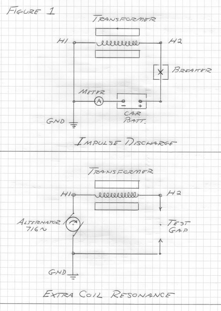
    Now connecting the line, H2, terminal to its line vacuum breaker, Figure 1, and connecting the line side of the breaker to the positive terminal of the car battery, a basic current loop is formed.

    The negative terminal of the car battery is connected to an ammeter and then to the transformer neutral. The neutral, H1, is grounded to station ground.

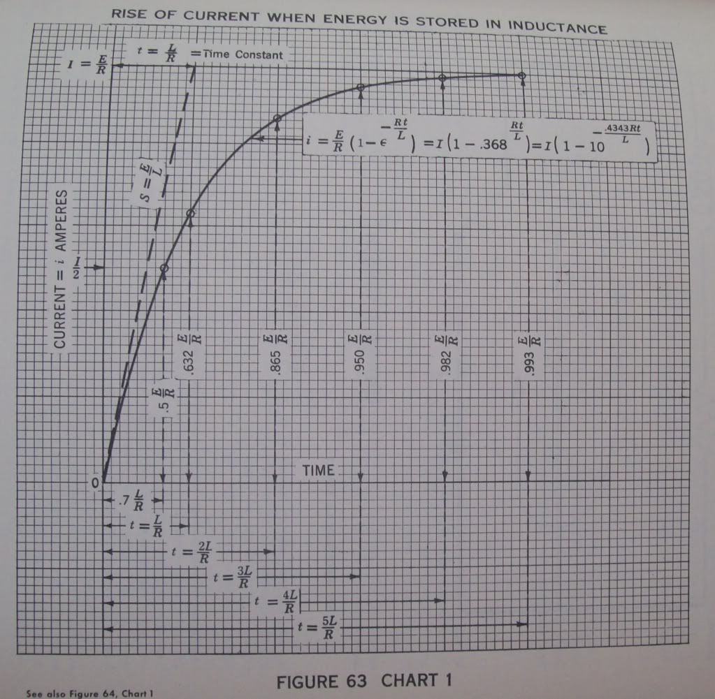
    3) The vacuum breaker is closed completing the current loop, this loop a basic, L,R, circuit of 24 Ohm and 160 Henry. Upon closure a stopwatch counts time from the instant of this closure, T, equals zero. Observing the ammeter it is seen to rise very slowly. At the point when the ammeter reads
    316 milliAmpere

    The stopwatch is checked. The span of time to reach 63.2 percent of the maximum value is called the magnetic time constant, u. The stopwatch reads
    6.7 seconds

    The ammeter continues to climb, in ever smaller increments closer and closer to 500 milliAmp. It is noticed it takes over 33 seconds for the inductance to reach full charge. See figure 63.

    At full charge the winding current is one half Ampere. The static winding inductance is 160 Henry. Hence the magnetic energy storage is derived as
    20 Watt-second

    4) Now the vacuum breaker is tripped, this instantaneously breaking the loop. A streamer several feet long erupts from the line, H2, bushing insto space. Since no escape of energy exists the magnetic energy is abruptly converted into dielectric energy at a fundamental frequency and its odd order harmonics. This was given as
    716 cycles per second

    The effective values of inductance and capacitance were determined to be 100 Henry
    and
    500 picoFarad

    By the law of conservation of energy the magnetic energy equals the dielectric energy. By algebraic operation the ratio of EMF to current is the square root of the ratio of 100 Henry and 500 picoFarad,
    450 Kilo_ohm

    And thus from a 12 Volt car battery the EMF developed at the line terminal, H2, is derived as
    225 KiloVolts peak

    This assuming a sinusoidal waveform. Here the harmonics were burned off in the streamer issuing from H2.

    (5) The increase in frequency from 60 cycle to 716 cycle gives an increase of the effective resistance to 72 Ohm, at 716 cycles per second. The effective inductance is 100 Henry. The reactance of this inductance at the oscillating frequency, Omega,
    4500 radians per second

    is derived to be Omega L or
    450 Kilo-Ohm

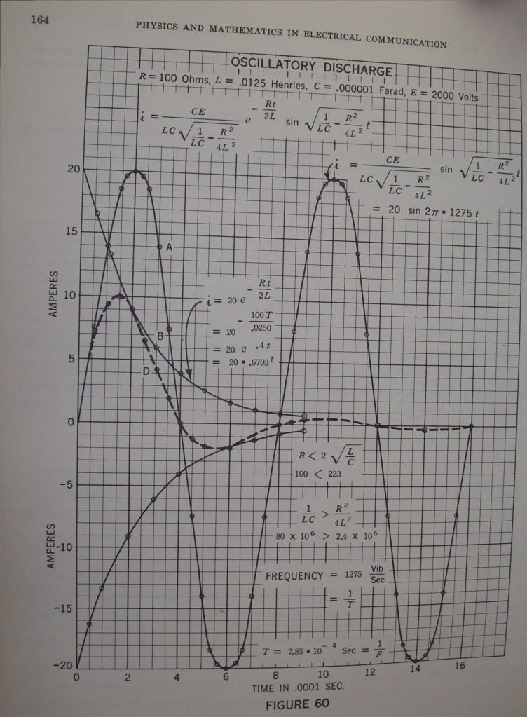
    And the time constant of the 716 cycle oscillation is derived from the effective inductance in proportion to the effective resistance, L, over, R. It is however that the oscillatory energy is magnetic only half the time, the other half is dielectric. Hence the time constant is given as one half the ration of inductance to resistance, one half of
    1.39

    Gives the oscillatory time constant as,
    .7 seconds

    At this time the magnitude of the oscillation has diminished to one over Epsilon, or
    36.8 percent

    The oscillation becomes inaudible in about five times this, or,
    3.5 seconds

    See figure 60.

    (6) The magnification factor of this oscillating winding is determined by the ratio of the effective winding reactance to the effective winding resistance,
    450 Kilo-Ohm
    to
    72 Ohm
    Giving
    6250 numeric

    The initial, or peak, current is one half an ampere this the effective value, or per square root of two, is given,
    356 milliAmpere RMS

    The initial, or peak, EMF is given as 225 Kilo-Volt, hence the effective value is,
    159 Kilo-Volt, RMS

    The product of these values gives the total oscillatory activity in the transformer winding,
    56.6 Kilo-Volt-Ampere

    (7) The losses in the windings are given by the square of the effective current times the effective resistance, I squared R, or the Back EMF developed by the losses is the current times the resistance, I, times, R, or

    25.6 Volt

    Here from are derived the basic transformation parameters in the operation of the 60 KV secondary winding as a resonant extra coil, this for an output potential of 160 KV at 716 cycles per second.

    Input (H1) Power Requirement
    9.1 Watt

    Input Impedance, E, over, I, or,
    72 Ohm

    This a resistive load as seen by the source of alternating electric energy. Hence, a 10 watt audio amplifier, on the 50 Ohm output tap, will give rise to a resonant oscillation, building up over a time span of 3.5 seconds, this with an activity of 56.6 KiloVars and an electrostatic potential of 160 KiloVolts. Here established is the concept, -- "Magnification Transformer"

    73 DE N6KPH


    From Perrine's book "Physics and Mathematics in Electrical Communications":
    Last edited by t-rex; 07-01-2012, 01:06 AM.

    Leave a comment:


  • t-rex
    replied

    Last edited by t-rex; 07-01-2012, 12:55 AM.

    Leave a comment:


  • t-rex
    replied
    60 KV Transformer, Theory:

    (1) In the previous experiments two distinct forms of resonance have been demonstrated.

    I) Lumped parameter resonance, circuital

    II) Distributed parameter resonance, wavelength

    In condition one the dielectric energy storage coefficient, capacitance, is external to the winding structure. The current IN at H1 is the current OUT at H2. There is no difference in magnitude, nor any displacement in time between the currents at H1 and those at H2, the same current.

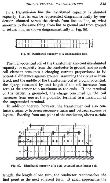
    In condition two the dielectric energy storage is within the winding structure and that in the space between the winding and the core and tank. This can no longer be expressed as a capacitance in the normal sense of the word. Dielectric energy storage is now a complex quantity in the dimension of space. For the most part is is inscrutable and all that can be measured outside of the tank is the effective capacitance at a given operating frequency. A graphic illustration is given by Tesla in his "True Wireless" extract. The effective capacitance of a coiled winding is the square root of the ratio of the capacitance, C, from winding to core and tank, and the elastance, K (in per Farad), existing within the interturn counterspace. Hence, Farad per, per Farad, the square root of which gives the effective capacity. In static or D.C. operation the energy storage coefficient, K, vanishes, leaving only the self capacitance, C. This measure as the static capacitance of the transformer winding. Hence the effective capacitance is a function fo the time rate of energy exchange. It is important to recognize here that a Pure Dilectric Wave exists. The space distribution of dielectric induction is given by the propagation constant. This constant is a Time Scalar, that is, the formation of this dielectric distribution is instantaneous from end to end on the coiled winding. No magnetic induction exists here.

    (2) The lumped parameter condition lends itself to circuital representation. Series coefficients are given as inductance, L, and elastance, K, Henry and per Farad. Shunt coefficients are given as Enductance, M, and Capacitance, C, per Henry and Farad.

    The components that comprise the circuit are lumped, or Space Scalar. The shape, size, geometry, and etc. play no definite role in the energy storage coefficients. In the magnetic "components" the dielectric field is forced out of existence, and likewise in the dielectric "components" the magnetic field is forced out of existence. The magnetic wants an expansive space, the dielectric wants a contractive space. See "Disruptive Discharges" in my Four Quadrant writing. Review This.

    (3) The distributed parameter condition CANNOT be given as a circuital representation. Inductance and Capacitance lose their common meaning and can only be expressed as effective values, such as derived from space integrals. The magnetic and dielectric energy storagecoefficients now exist in a different set of dimensions, as space derivatives of the energy storage coefficients. Dimensionally it is;

    Magnetic
    I) Distributed Inductance: Henry per centimeter
    II) Distributed Enductance: per Henry-centimeter

    and Dielectric
    III) Distributed capacitance: Farad per centimeter
    IV) Distributed Elastance: per Farad-centimeter

    The designations, C, K, L, M, are to be taken on this per centimeter basis when expressing energy storage in distributed form.

    It is of interest to note here that, L, and, C, now are dimensionally equivalent to the magnetic permeability, and the dielectric permittivity,

    Mu, or Henry per centimeter
    Epsilon, or Farad per centimeter

    Hence these coefficients, L, and, C, are akin to the one over C square relation of electro-magnetic wave propagation. Conversely M, and, K, are of a unique dimensional constitution and K, is more akin to a sound wave condition. The product of, M, and K, do not yield an electro-magnetic condition, there is no per velocity square as given by the product of, L, and, C. The dimensional relation of, M, and, K, yield a magneto-dielectric condition as a per counter-velocity square. Hence if velocity is given as

    C, in miles per hour

    It is that counter-velocity is given as

    u, in per mile per hour.

    These propagations exist at right angles to each other on the coiled winding in a Four "dimensional" space as the physic would like to say. This complex configuration defies any existing analysis.

    (3) Here in the winding with distributed constants exists a transmission line condition, propagation is involved from one end of the winding, H1, to the other end of the winding, H2.

    It is however, that this propagation not only exists in space, such as a two wire phone line, but now also exists in counter-space. The dimensional relation of velocity no longer has meaning in defining this propagation. These considerations are the primary stumbling blocks to resonant transformer calculations. The physicist declares the situation as "incapable of being treated by mathematics" and thus declares it impossible to exist. Then comes ridicule, and finally totalitarian suppresion, AKA Al-Gorda.

    4) Now it is left to the experimenter. Tesla knew very little of what has just been given here on the resonance of windings. He had one foot in lumped constants, and the other foot in distributed constants, and no measuring instruments that are taken for granted today. It can be plainly seen that here is a transmission line problem, just taken to the next level. Basic two wire line theory is almost beyond human conception as plainly given by Heaviside, Steinmetz, and Guillemen, in thousands of pages. Now it goes octaves deeper.

    73 DE N6KPH
    Last edited by t-rex; 07-01-2012, 12:49 AM.

    Leave a comment:


  • dR-Green
    replied
    Originally posted by T-rex View Post
    Dr Green Extra Coil

    3670 Luminal Wavelength
    81.70 Meters

    3670 Luminal Quarter Wave
    20.4 Meters

    Empirical Extra Coil Velocity Factor
    124%

    Extra Coil Wire Length
    16.5 Meters

    Wind your width equals height extra coil with 16.5 meters of 18 to 22 gauge transformer wire
    Thanks again Eric. I think I know how you came up with that now, basically making the extra coil wire length for 124% the velocity so divide the wavelength by 1.24? I was unwinding the coil ready to try the 30 SWG wire as you wrote that, so there's 64.25 turns of 20 SWG (0.9mm) on there now.

    The strange thing now is that the 3670 peak has completely vanished, it's as if the secondary doesn't exist any more. I've removed the condenser rings arrangement (but left the one on the top of the secondary) in case there was too much capacitance, but even with nothing across the secondary I can only find one peak up to 5 Mc.

    Without the condenser rings the peak is at 3474 kc. This appears to be the Tandem mode. Old extra coil peak was about 138mV, secondary 48mV. With the new extra coil, peak is 254mV and secondary 117mV.

    Just got it finished and did a quick run before going to bed so that's all this is so far, haven't played around with it much yet. I'll do some tests on the new extra coil separately tomorrow.

    Leave a comment:


  • garrettm4
    replied
    Parameter Variation Research

    I have recently started doing some research into parameter variation again and have had some encouraging experimental results. Also, I have gotten a lot of it written down and edited for sharing here on the forum. However, I don't want to detract from all the good progress being made towards the CRI, so I won't be posting too much about that on this thread.

    For those who are interested in this subject, the title of my future post will be:

    Angle of Hysteresis & the Continuity of Energy;
    An exploration into the Synthesis of Energy via Parameter Modulation

    It won't be ready to post for a week or two (still lots of editing to do), but here's an abstract, some graphs and a few quotes to keep you interested:

    Abstract

    When working with parameter modulation, asymmetric distortions in the systems power waveform, due to the angle of hysteresis of induced fields to intrinsic fields, causes the appearance and disappearance of electrical energy. This is seen in the form of an artificial shunt conductance or an artificial series resistance, these artificial quantities can be found to have negative values when certain angles of hysteresis are observed, causing an increase of energy per half cycle into the electrical system, while the opposite causes a decrease of energy. A basic theory to define these artificial quantities along with negative parameter values (such as negative inductance and negative capacitance) will be discussed and referenced with known electrical systems that exhibit the phenomena.

    Tech Note, synchronous motors are also sometimes called "synchronous condensers" or "rotary condensers", because they have a leading current in certain situations like a condenser or capacitor would. This causes them to appear as a NEGATIVE inductance to the circuit in which they are used. The negative inductance property of an over excited synchronous motor is commonly used to cancel the reluctance of "positive" inductive loads (induction motors and transformers) and thus restoring a unity power factor. Much like how a capacitor stabilizes a DC circuit, a synchronous motor can stabilize an AC circuit by storing energy in the form of mechanical mass as a motor and returning that energy back to the circuit through generator action.

    Below is a reactance plot showing the action of negative and positive reactive circuit elements:


    A quote from what Tom Brown had written regarding Mr. Dollard's work:

    "The Alternating Electric Waves paper, presenting Eric's Four Quadrant Theory of Electricity, was written after his discovery of how to generate excess magnetizing power in an industrial situation (using synchronous motors in a huge shipyard) and make the KVAR (Kilo Volt Amperes Reactive) meter turn backwards. Eric discovered that these industrial meters are pinned so that they will not turn backwards, but they can be stopped, creating readily realizable savings for the industrialist."

    From Steinmetz's chapter on Reactance Machines:


    A step and sinusoidal variation of reactance:


    As you were gentlemen, I apologize for the distraction,
    Garrett M
    Last edited by garrettm4; 07-01-2012, 05:47 AM.

    Leave a comment:


  • t-rex
    replied
    Dr Green Extra Coil

    3670 Luminal Wavelength
    81.70 Meters

    3670 Luminal Quarter Wave
    20.4 Meters

    Empirical Extra Coil Velocity Factor
    124%

    Extra Coil Wire Length
    16.5 Meters

    Wind your width equals height extra coil with 16.5 meters of 18 to 22 gauge transformer wire

    Leave a comment:


  • dR-Green
    replied
    Originally posted by T-rex View Post
    Extra Coil

    Dr Green;
    I believe that another extra coil needs to be made for a higher frequency, that of your secondary, 3670. So an extra coil for 3700 with some terminal loading. The extra coil that you have now is too large/long and many turns would have to be removed, best to keep this one intact. Since now you can see the actual extra coil relations from the one you made, now it can be scaled to any frequency. Break, more to follow...
    Extra coil wire length for 3700 = 32 metres
    3670 = 32.27 metres

    As it currently stands with 124 turns I have 31.75 metres, but the wire spacing is also changed and apparently that has no small effect as well. Maybe another option would be to rewind the existing extra coil with thinner wire so the frequency is a bit higher on the same frame? It currently has 26 SWG (0.45mm) over 8.28cm, but I might have enough 30 SWG (0.32mm) available so it would be spaced out a bit more.

    Taking the 10.3mV reading example from above (124 turns), I can get it up to 12mV just by moving two or three turns closer together towards the top of the extra coil. So if using the extra coil as originally intended for 3670, would it be worth trying thinner wire to see if the frequency can be raised do you think? This is where other people's results would be handy to look at (hint )

    Another option is to replace the 26 SWG secondary with 20 SWG.

    Secondary wire length for 3700 = 12.97m
    3670 = 13.07m

    The 26 SWG not holding a perfect circle around the support rods has reduced the secondary length from the intended circumference to what I estimate is a total length of 12.92m, so if I replace it with 20 SWG then the secondary should also be brought down in frequency a bit. But the frequency is set by the rings in that case so I suspect the focus should be on the extra coil for now.
    Last edited by dR-Green; 06-29-2012, 10:32 PM.

    Leave a comment:


  • t-rex
    replied
    Extra Coil

    Dr Green;
    I believe that another extra coil needs to be made for a higher frequency, that of your secondary, 3670. So an extra coil for 3700 with some terminal loading. The extra coil that you have now is too large/long and many turns would have to be removed, best to keep this one intact. Since now you can see the actual extra coil relations from the one you made, now it can be scaled to any frequency. Break, more to follow...

    Leave a comment:


  • t-rex
    replied
    60 KV Transformer

    (1) Experiments continue today with the 3000 KVA 60 KV generating station line transformer. No information exists on the exact distributed constants within this transformer therefore the constants will be developed by the use of effective values as externally measured.

    A source of variable frequency alternating current is applied to the 2.4 KV primary winding of the line transformer. The neutral, H1, of the secondary winding is grounded. An electro-static voltmeter is connected from neutral, H1, to line, H2, of the 60 KV secondary winding. It is found that the fundamental quarter wave frequency is 716 cycles per second. This is the natural frequency of the transformer.

    (2) The scalar inductance was determined by 60 cycle measurement to be 160 Henry. Since the current in the winding in resonance (self) is of a sine distribution along the winding length the effective value of inductance is two divided by Pi times the scalar inductance. Hence the effective inductance is derived:
    100 Henry

    (3) For a frequency of 716 cycles per second the angular frequency in radians per second is two Pi times 716 giving:
    5000 radians per second

    The product of the inductance and the capacitance of an oscillating circuit gives the inverse of the square of the angular frequency. By algebraic operation it is hence the capacitance in Farads is given by the inverse of the product of the inductance and the square of the angular frequency. Here derived is the effective capacitance,
    500 picoFarad

    And since the electro-static potential also is a sine function along coil length multiplication by Pi divided by two gives the total capacitance,
    785 picoFarads

    These values are for 716 cycles per second only, the Pi over two, or quarter wave resonance, of the winding.

    Hereby the basic energy storage constants of the transformer secondary are established for a condition of self resonance. Now rather than a 60 cycle power transformer it is a 716 cycle resonant, or Tesla, transformer.

    (4) In this self resonant mode this transformer not only has a frequency in radians per second, but also has a wavelength in radians per centimeter. At 60 cycles the winding is space scalar, that is, the current is the same in each and every element of length along the winding conductor. At 716 cycles the current not only varies along the length in intensity, but also varies in phase. In terms of effective values the current at the neutral, H1, is not equal to, or in phase with, the current at the line, H2. Also at quarter wave the current is zero at the line terminal since this terminal is not connected but left free. The circuital laws of Kirchoff no longer apply and the currents no longer sum to zero. Hereby a mono-polar current appears to ground at the neutral, H1, of the secondary winding.

    (5) In order to analyse this transformer winding as a transmission network two factors must be known:

    I) The propagation constant as derived from the product of the effective inductance and the effective capacitance,

    II) The characteristic impedance as derived from the ratio of the effective inductance and the effective capacitance.

    The propagation constant is defined by the frequency, or per second. The characteristic impedance is derived from the square root of the ratio of the effective capacitance. While the frequency is invariant if the Miller, or Steinmetz methods of determining the effective values, the impedance is not and will differ between methods of deriving effective values. For simplicity the Steinmetz method is used here. Taking the effective inductance as,
    100 Henry

    And the effective capacitance as,
    500 picoFarad

    Gives the characteristic impedance as,
    450 Kilo-Ohm

    This can be called the natural impedance of the secondary winding at its natural frequency of
    716 cycles per second.

    These are the fundamental externally established constants for the 60 KV secondary winding.

    (6) Hereby the input vs output transformation of this secondary winding can be determined. The winding can now be considered a "Black Box" two terminal reactance arm, this akin to the Guillemen line shown previously. In this network of coiled windings the output potential is the input current multiplied by the natural impedance. Hence for a current applied to neutral (H1) terminal, one ampere multiplying this by 450 Kilo-Ohms gives a potential at line terminal (H2) as
    450 KiloVolts

    This causing the bushing spark gap to flash over. Since the B.I.L. of this transformer is 300 KV then this potential divided by the natural impedance derives the maximum permissible neutral current as,
    .667 Ampere

    At a frequency of 716 cycles per second. In this manner, when excited through the neutral to develop a high potential at the line, the 60 KV secondary winding is operating as an extra coil. The primary has no function in operation and therefore this is no longer a resonant transformer. Thus this 60 KV transformer can serve two distinct functions:

    I) A resonant transformer with a low voltage primary and a high voltage resonant secondary,

    II) an extra coil as a single resonant high voltage winding series fed through its neutral.

    73 DE N6KPH

    Leave a comment:


  • dR-Green
    replied
    A quick note. I'm down to 124 turns from 126 and doing tests of each one. 125 turns got better than 126, but 124 is worse than both. Apparently with 124 turns I can make up for it a bit with tiny pieces of tinfoil on the top end of the extra coil wire, presumably making up for the capacitance lost through removing turns and increasing the wire spacing. This might be tricky Even the slightest adjustment in wire spacing affects it in a noticeable way. I think a lower frequency setup might be more practical for this.

    [edit] With a condenser arrangement between the top of the extra coil and earth for test purposes I can get up to the same potential in the extra coil as in the secondary, but not any more yet in Concatenated mode. The secondary potential is also higher now than when I started.

    For instance, in "normal" conditions (extra coil top end free), extra coil potential is measured at around 10.3mV. Secondary is around 26.5mV.

    By adding a condenser arrangement at the top of the extra coil, secondary potential can be brought up to 28.8mV, and extra coil equally to 28.8mV. With further adjustment the secondary can be brought up to 33.7mV, but then the extra coil drops to 23.9mV. I can't get the extra coil to overtake the secondary as yet, and with the condenser at the top I assume I probably won't be able to either. Tests will continue tomorrow/later.
    Last edited by dR-Green; 06-29-2012, 08:35 AM.

    Leave a comment:


  • madhatter
    replied
    David,I had earlier put together a post on the tandem and concatenated differences. Although they are synonyms, the root derivation from latin isn't.

    con- with
    catenation -chained together:
    so it's "chained with or linked to each other"

    Tandem: From Latin, literally "eventually, at length,"

    the key difference here is that a concatenated series can be linked sub groups of various phases, frequency etc.. whereas the tandem is conjointly.

    clear as mud right

    Leave a comment:


  • dR-Green
    replied
    A diagram would help because we don't have a clue what you're talking about with this connected to that etc.

    Originally posted by David G Dawson View Post
    I would like to know the difference between 'Tandem' and 'Concatenated'.
    It's shown on the previous page and can be seen in effect in the test data I provided - two resonant peaks, the idea being to have the extra coil resonate with the secondary, not as one big length of wire at a lower frequency. All I would like to have is a basic understanding of your setup via diagrams of how it's all connected and set up to know what you're talking about when you're describing things. That along with your radio station frequency and wire lengths, and for example an answer to the question "can you receive the radio signal without any extra coil?" Also some frequency response graphs would be very nice. With this basic information then we can easily determine what you're doing.
    Last edited by dR-Green; 06-29-2012, 06:02 AM.

    Leave a comment:


  • David G Dawson
    replied
    Extra Coil Math

    Quote:
    Eric doesn't have anybody to type for him in his current location so he asked me to tell you, David Dawson, that you are really driving him nuts with your "Multiply". In the post above, Eric acknowledges that you have achieved the Tandem mode of resonance. However, he is trying to push people towards the Concatenated mode of resonance.

    How many of you coil builders have seen results from the originally prescribed formulae by Eric? How many of you have seen results from Mr. Dawson's formulae?

    David, is it possible that because the concatenated mode of resonance has a higher magnification factor and that you were not able to get the secondary and the extra coil into a strong resonance, therefore no results? I am with dR-Green in the plea that you make diagrams so we can all see what you are talking about. No offense, but a lot of what you post is very ambiguous to me sometimes and hard to tell exactly what your point is. Please use diagrams in conjunction with your numbers. It will help clear up this confusion. Photobucket is free and it is what I use for all of the LaTeX equations and pictures in the T-Rex posts.

    Dave
    End of Quote.

    Eric has supplied all the drawings required and I cannot improve on those.
    My last two Posts told you clearly and distinctly what is different and no drawing is going to help there.
    Now all of a sudden we have a new mode of resonance, 'Tandem' as against your 'Concatenated' and you now have some explaining to do and why did you not do this on day one?
    Why is it that what I propose models Tesla's down to a 'T' and yours doesn't and that makes me wrong by having this new 'Tandem' resonance.

    Excuse my ignorance but you now have some explaining to do.
    I do NOT and have NOT made any claims in mastering anything.
    I am simply pointing out that my method follows Teslas where yours doesn't.

    So now you are saying that Tesla's TMT was a 'Tandem' resonance device and not a 'Concatenated' one?

    Why is your Extra Coil so different to Teslas where you do not have the same length as he was using for both Secondary and Extra and you have a reason that you have 'mastered a better system' which I built and does not work.

    Time Eric you sat down calmly and read what was being presented before your very eyes and wake up to your own confused references as I have pointed out above.

    Nobody has bothered themselves to build using my method, just queries and excuses so why ask a stupid question?
    When you have a person who you believe to be God, why would you want to hear from anybody else?

    I would like to know the difference between 'Tandem' and 'Concatenated'.

    Smokey

    Leave a comment:


  • Web000x
    replied
    Originally posted by T-rex View Post
    The second mode of the extra coil and secondary coil connection involves two quarter wave distributions, one on each coil. This is not to be considered a half wave however. This mode is the <b>CONCATENATED</> connection.It compounds the quarter wave resonant rise of the secondary coil with another quarter wave rise in the extra coil, hence a concatenated resonant rise. This is the holy grail of resonant transformer design and unheard of potentials may be gained in this manner. To derive this analytically is extremely difficult, it is an advance transmission line problem. It might not even be possible to calculate or even achieve this mode of resonance, but we are going to give it a try. Tesla dreamed of this mode but electrical knowledge was in its infancy in Tesla's Colorado years. Also note that D. Dawson has become a zealot in drawing us back into the tandem mode of operation, which he claims to have mastered. It has come to pass that he is now becoming a detractor, his denouncements abound. I hereby ignore his posts and caution others that a confusion may develop here for the beginner in this un-charted territory.
    [/url]
    Eric doesn't have anybody to type for him in his current location so he asked me to tell you, David Dawson, that you are really driving him nuts with your "Multiply". In the post above, Eric acknowledges that you have achieved the Tandem mode of resonance. However, he is trying to push people towards the Concatenated mode of resonance.

    How many of you coil builders have seen results from the originally prescribed formulae by Eric? How many of you have seen results from Mr. Dawson's formulae?

    David, is it possible that because the concatenated mode of resonance has a higher magnification factor and that you were not able to get the secondary and the extra coil into a strong resonance, therefore no results? I am with dR-Green in the plea that you make diagrams so we can all see what you are talking about. No offense, but a lot of what you post is very ambiguous to me sometimes and hard to tell exactly what your point is. Please use diagrams in conjunction with your numbers. It will help clear up this confusion. Photobucket is free and it is what I use for all of the LaTeX equations and pictures in the T-Rex posts.

    Dave

    Leave a comment:


  • David G Dawson
    replied
    Extra Coil

    Originally posted by madhatter View Post
    impedance matching, this is where I think it's tripping up radio guys. Recall that the point here is to show that the ground current is FTL, in order to do this the receiving antenna needs to match the transmitter. If the extra coil is short it will only match the air radio waves, not the ground current.

    So how would one design an antenna to match impedance of two different velocity propagation waves? This is a complex conjugate and a transmission line problem. This is what Eric has been talking about this whole time, not being a radio operator to begin with I'm not burdened with trying to think outside that box, however being a physicist taught quantum theory, well that's taken a paradigm shift to start to understand the true nature of the field.

    I know Eric says one doesn't really need to understand the mathematics behind it, I disagree as there is very complex relations and simplifying the math leaves out the beauty of what's going on, heck for the most part the math doesn't exist to handle this. but understanding where the limits are with current equations on the matter really help in moving forward.
    David,
    Yes, that was also my concern initially but then I realised I was radiating and it wasn't EM it was that 'something' else which I believe to be LMD or Tesla's 'Radiant Energy'.

    Remember please that Eric's Math does NOT match Tesla's where mine does and specifically in the length of the Secondary and Extra being near the same.

    My operating point is ABOVE the AM frequency where Eric's is BELOW and this is the other criteria to be used.
    See my drawing for confirmation of the Math and I drew this out to scale but is better the way I have shown.

    The other feature to note here is the contact/no-contact operation of the probe-head and Headphones.

    Contact means EM, no-contact means LMD.
    This fact was amplified by the 'Fence Experiment'.

    You must have the pick-up head and high impedance Headphones to recognise what is happening here.

    Nothing more I can say as you now have it all in an easy to follow format.

    Not here to disprove Eric's theory or Math as this is what this is all about -'empirical experiment' and I had an accidental theory that worked that matched Tesla's where Eric's didn't - that's all.
    Eric has set the groundwork here and not me and made this all possible.

    Smokey

    Leave a comment:

Working...
X