Announcement

Collapse
No announcement yet.

Jes Ascanius Radiant collector

Collapse
X
 
  • Filter
  • Time
  • Show
Clear All
new posts

  • It would be really nice to get schematics of the joule thief and Bedini oscillator circuit connections. That's something I haven't tried.

    All here need to be aware that the 1N34 diode is a photodiode. That means it converts light to electricity. So as you add them, your output should go up as long as they are lighted. Putting the circuits in a closed project box that removes that light input should make the output go down.

    Comment


    • Bedini Circuits

      Originally posted by thx1138 View Post
      It would be really nice to get schematics of the joule thief and Bedini oscillator circuit connections. That's something I haven't tried.
      Here's 2 I have tried, but couldn't get to work with AWG 28... I have some AWG 40 coming and will give them a try with that....


      The one on the left, I found here on the energetic forum... the one on the right I copied from a 2011 video from a Bedini presentation video (click here) on his alum crystal battery. I would love to know the resistor values. I have a variety of resistors coming in next week too.

      Comment


      • I was really more interested in how you were connecting them with the Ascanius circuit.

        The LED resistor values will depend on the LED's used. They are current limiting resistors to keep from blowing out the LED's. Too much resistance and they won't light. Not enough resistance and they will burn out.

        The resistor before the transistor Base will depend on the transistor used. It is also a current limiting resistor and if you use a BJT transistor as shown in the schematic the minimum current to turn it on and the maximum current allowed on the Base will be in the datasheet. It's an important parameter for a BJT transistor since they are current driven whereas FET transistors are voltage driven.

        There are so many Bendini scematics around it seems you should be able to find resistor values but you have to be sure to match them the the LED's and transistor you actually use.

        The formula for a current limiting resistor is I = V / R where I is the current out in Amperes, V is the voltage in, and R is the resistance in Ohms.

        So 5 volts into a 100 Ohm resistor would give you 0.005 Amperes or 5 milliamps output.

        Comment


        • Originally posted by thx1138 View Post
          I was really more interested in how you were connecting them with the Ascanius circuit.
          Hi thx

          It´s easy, connect the + of Ascanius output to + of joule thief and output - with - of JT.

          It´s possible that don´t work if you don´t have enought volts in the Ascanius output, the transistor will don´t work till the volts increased enought in the output capacitors of Ascanius circuit, about 360/380 Mv with a 2n3055, and then the capacitors will discharge in less than second and you will have a hard flash, you will have to wait till the capacitors charges again, but if you put a lineal potentiometer, 10 o 20 K, between +output and the base of transistor you can regulate the volts of the transistor, so you can regulate the led flashing.

          I have made it and works fine, if you connected leds of this kind (Tiras LED blanco dual | Info Led - Ledbox) you can turn on 10 or more, I have made a little video with 27 leds turned on and you can see some moments flashing slow (more intense) and others moments more quick (less intense). You can watch the video here captador energia mas joule thief2 - YouTube

          Please, let me know if you any doubt.

          Comment


          • Originally posted by tgraca View Post
            I would love to know the resistor values. I have a variety of resistors coming in next week too.
            Hi Tgraca,

            The circuit on the right is a Joule thief, you can put 100/1000 Ohm resistor in the base of transistor and for collector between 30/50 K resistor, depending of intensity, as says thx.

            Comment


            • Teo's Power Circuit

              Originally posted by cat-tito View Post
              Hi Tgraca,

              The circuit on the right is a Joule thief, you can put 100/1000 Ohm resistor in the base of transistor and for collector between 30/50 K resistor, depending of intensity, as says thx.
              Finally got a nice day last week to work on my grounds, but had to work... I have been going through the Bedini Earth Light thread over the last 3 weeks and am up to page 34 of 145+ pages... there's a lot to absorb...

              I tried a number of JT and Bedini's SG circuits, but the best they could do for low energy was blink a light... I ended up with this circuit today, which worked for resistances from ZERO to 10K ohms... I got my inductors in yesterday, so after winding tons of bifilar inductors, I just plugged a few in until something worked well.


              What's great about this circuit? It can take very low power and give fluid non-blinking power at all resistances. I think I have a winner here! First success in 4 months! I have a crystal cell with 0.75 V and 30 uA, which could not power an LED, but with this circuit, it gives a steady stream of light at all resistances tested (ZERO to 10K ohms).... and I think it can scale to something usable in the Jes Circuit!

              I am not sure if this qualifies as a JTC.
              Last edited by tgraca; 03-29-2014, 12:20 AM. Reason: Changed URL tag to IMG tag

              Comment


              • Originally posted by tgraca View Post
                Finally got a nice day last week to work on my grounds, but had to work... I have been going through the Bedini Earth Light thread over the last 3 weeks and am up to page 34 of 145+ pages... there's a lot to absorb...

                I tried a number of JT and Bedini's SG circuits, but the best they could do for low energy was blink a light... I ended up with this circuit today, which worked for resistances from ZERO to 10K ohms... I got my inductors in yesterday, so after winding tons of bifilar inductors, I just plugged a few in until something worked well.


                What's great about this circuit? It can take very low power and give fluid non-blinking power at all resistances. I think I have a winner here! First success in 4 months! I have a crystal cell with 0.75 V and 30 uA, which could not power an LED, but with this circuit, it gives a steady stream of light at all resistances tested (ZERO to 10K ohms).... and I think it can scale to something usable in the Jes Circuit!

                I am not sure if this qualifies as a JTC.
                Hi Tgraca,

                I attached an interesting doc
                Attached Files

                Comment


                • PDF Doc... status...

                  Originally posted by cat-tito View Post
                  Hi Tgraca,

                  I attached an interesting doc
                  I have seen this many times and will try it. There's a number of circuits out there that can be tried, and I have modified Jes's circuit in a number of ways, but want to give Jes's circuit a try as he shows. I can't imagine multiple Jes circuits will provide a lot of usable power, but Patrick Kelly seems convinced, so I will try my best to replicate it. We are supposed to have 3 great days starting tomorrow, and I have a lot of outside work planned.

                  I am speaking with an electrical engineer that has a working radiant energy system, is moving production to Asia and says he will have it in production by the end of the year... I hope to replicate his system by the end of the year. He said, straight up, that the depth of the ground isn't as important as the mass of metal buried. I told him about the old kid's swing set that I salvaged - steal - and that I wanted to bury it horizontally about 12" deep and use it for a ground... he said that would work better than a 10' deep copper ground with less metal mass, so I will give that a try too... I'll bury it under 4" of concrete and use it as one ground.

                  I fixed the schematic of my mini amp circuit.... I had it drawn wrong... connecting the second cap to the wrong inductor... the resistor and cap run in parallel off of ONE of the inductors to the base of the transistor like Bedini's SG circuit... I am building several of these today and will try to attach one of them to a few of Jes's circuits that I have here... when I get my grounds up to par I will test one and more of Jes's circuits by themselves and then work them with my new amp circuit to see what happens.

                  My current LCD only measures less than 200 uF in caps, and since I like to test my caps before I attach them to circuits, I am limiting my experiments to that specification. The only test I can run for more capacitance is to time power from a fully charged cap against a fully charged cap I can measure... to determine Farads....

                  The crystal batteries thread talks about using some of them as capacitors... I have tested this and they do work as capacitors and resistors, but mine are inconsistent at best, and unmeasurable at worst. I am working toward the car battery conversions to alum / lead for use in storing power from the Jes circuit... BTW - I up to 09-03-2011 on that thread as of today! It's got a ton of great information... some of which are useful toward this thread... -t

                  Comment


                  • New Circuit Design from Kelly's Chapter 7 Tested

                    After a nasty cold and wet winter here spending most of my spare time on crystal batteries, I finally connected my second ground last week and when I got in last night from my travels, I noticed a modification to the Jes circuit in Patrick Kelly's Chapter 7 doc and gave it a try this morning - less components makes it easier to build....


                    I noticed the circuit is basically 2 circuits in parallel, so I tried just one and had some good success (see above pic). I can't match the configuration exactly with what I currently have and 6 or 8 AWG is really expensive, but with my lesser config, I am getting some success, which to me is a proof of concept. This is my first real success with this idea since Dec. 2013. Thank Jes and Patrick!

                    Note that the aluminum wire "Alexkor" Aerial System is probably irrelevant, but is currently hooked into the configuration. I will bypass it and compare the results in my final tests.

                    Antenna - 80 feet of stranded/insulated copper speaker wire (14 AWG) wound as bifilar (40' pair wound and connected as effectively 40' clockwise and 40' counter clockwise - not sure if this matters, but wanted to specify the config...) connected to a pair of coax cables, about 50' each with one end not connected.* The coax is an old Dish TV cable and the center looks like it's copper. Do you think this coax may be considered an additional 100' of antenna. (not sure)

                    About 20' of single 14 AWG stranded copper speaker wire connected to "Alexkor" Inspired Aerial (212' of aluminum 17 AWG) and about 20 feet of 12 AWG solid copper wire connected to the 3' copper pipe (1/2") ground. The main house ground is probably 30' to the ground from the lab and goes through an old cable TV coax.

                    The lab is about 10' high - second level of my home... not quite the halfway point as recommended, but close. Also, the antenna, grounds and lab are all offset horizontally - nothing directly above the other... not sure if that matters here, but I think it was recommended... I think the specification is is to have the antenna directly above the ground, or at least one of the grounds....

                    *I have the bifilar antenna set up this way to try to replicate the Raymond Phillips idea of running the circuit up and through the antenna so there are effectively 2 connections between the antenna and the circuit... I like this idea..... but the second antenna connection is not currently connected in these tests...

                    Current Config: 1N34A's for the diodes, 50 V 100 uF polarized capacitor, four 50 V 0.1 uF rated ceramic caps paired on top and bottom... the paired caps tested at around 0.165 uF with LCR meter - still not to specs... I can't find the ceramic caps at 200 nF and 200 Volts, but I did find some film caps with this rating at $1.00 each... too much for me... I do have some ceramic caps coming rated at 220 nF and 50 V, so I won't have to pair the caps when I get them in... - not sure how critical 200 volts is, but gotta go with what I have and can get for now - I am open to ideas on this... Also, since I am using 50 Volt caps, I am wondering how many circuits it will take to pop them. They are pretty cheap and I wouldn't mind getting that on video! lol

                    Results: 4.8 volts if left standing with the volt meter off for about 20-30 minutes... settles at around 1.5 standing volts when connected to the volt meter. When shorted, this set up shows 1.8 uA and 1.8 mV. I like the new configuration for the circuit and may try it with transistors instead of 2 diodes -- they are much less expensive than the 1N34A's (about $1.68 for 4), but I do have enough 1N34A's to build a 9 of these circuits.

                    In the above picture, I included an idea for using transistors (NPN's to PNP's) instead of the 1N34A's. The 1N34A's cost so much more versus the transistors. ($0.065 USD per pair - NPN 2N3904 and PNP 2N3906 - both by Fairchild) - I have these but will probably go with 1N4148's as my next test. Soldering these tiny transistors looks tough...

                    I have 500 1N4148's coming - cost was $0.02216 USD per 4. eBay has some good deals if you don't mind waiting a bit for your order to come in.

                    I just tested the circuit with my amp circuit (previously posted) and one of these circuits pulses a very low powered LED about once every 50 seconds.

                    Comment


                    • 2-7 Circuits - Test Results

                      Built 7 circuits, but actually lost power per circuit added. With 7, it couldn't charge the caps past 100 mV in parallel or in series. Same issue to a lesser extent with 4 or 2 circuits, respectively. I got up to 8.6 volts with one and 1.5 volts standing with volt meter, but it could barely pulse my low powered LED every 50 seconds with my amp circuit... My next step for the Tesla / Jes Arc. idea would be $231.00 for 500 feet of 6 AWG wire... probably won't go that direction right now...


                      I got WAYYYY more power out of a $0.03 crystal battery.


                      That's it for now.... - t

                      Comment


                      • Details, details

                        tgraca: a few notes for you.

                        The 1N34 diodes are also what is known as a photodiode which means they convert light to electricity. As long as they are in the clear case so the light can reach the material inside they will produce more electricity than when they are covered. You can test it by moving then in and out of the light or wrapping them with black plastic tape. So I would expect the 1N4148's not to perform as well, if at all.

                        Note Jes' comments about insulating everything. That's because some amount of the charge is on the outside of the wire and it will neutralize with charges in the air. So shorter wire leads are better and insulating them with paint or shrink wrap is also better. If you use a printed circuit board, all of the traces will be insulated and only the solder points will be exposed.

                        Comment


                        • Research with Jes Ascanius System

                          Yes received some great success with the Jes Ascanius system....

                          See my link Free Energy System, Jes Ascanius system, Aerial Electricity


                          Got fully charged caps, 32Volts

                          Nothing much on current....so more of the circuit modules must be added and worked out....but its a start....

                          As Jes explains the earth and aerial must be good....

                          Cheers
                          Rob

                          Comment


                          • Originally posted by Kregus View Post
                            Hey guys,

                            I was able to generate 10v in 30mins using the following circuit based on the original Tesla Radiant Energy patent:


                            However, I am very interested in building the Jes Ascanius circuit, because it promises to provide much more energy.

                            The 200v 200nF capacitor is hard to find, because it does not exist. In fact, if you look closely at the pictures in the PJK book on page 9, chapter 7, you see that the capacitors used are actually 250v - 275v. Also, keep in mind that 200nF is the same as 0.2uF! So, a capacitor you could use is this one.

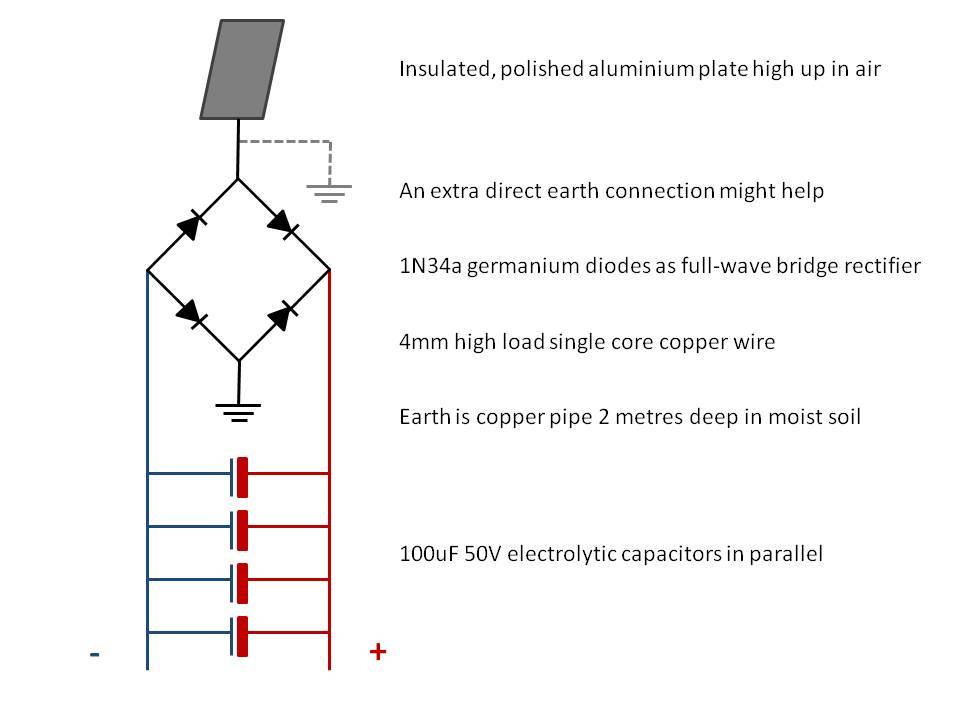
                            I ordered all the parts and am going to build the system tomorrow, but I have some questions about the Jes Ascanius circuit. For example, I get that this setup diverts + energy waves into one half of the capacitors, while the - energy is stored in the other half of the capacitors. My question is: why not use a Full Wave Bridge Rectifier setup so you only need a single capacitor? This image shows what I mean:


                            As you can see, I omitted the big 250v 0.2uF capacitors, because I don't really get why they are positioned before the diodes. Would be great if someone could explain that!

                            Hope someone can answer my questions!

                            Also, someone on an other forum mentioned that the 1N34a germanium diodes might be replaced by the much cheaper 1N5819 SCHOTTKY diodes ($0.34 vs $0.04!). I also purchased those, so I'll see how they perform.

                            As far as I can learn so far, the cap connected to the aerial first collects the charges in AC mode...resonating with the earth, then the diodes push the AC charges unto a electrolytic capacitor before going to the load

                            Free Energy System, Jes Ascanius system, Aerial Electricity my success is limited so far...

                            Need to learn how to build and strengthen the current side of the charge....

                            CHeers
                            Rob

                            Comment


                            • A paper of interest to this subject

                              "Radiation Induced Electrical Current and Voltage in Dielectric Structures" attached.
                              Attached Files

                              Comment


                              • Hi guys! Any news?
                                I find interesting scheme of connection diodes and try to build a set of diodes like this scheme, but it is dont working. One module is working greate and give about 4.5v, but two or more - NO! Why? Diodes is D9G, russian analog of 1N34.

                                This is scheme. Sorry dont find how decrease size before posting.

                                http://svapka.ru/wp-content/uploads/2010/01/dodmost.GIF

                                Comment

                                Working...
                                X