Duration is the time it takes for the core material to pass over the
magnet. Mine is bottom right.
Also the frequency of the impulse coming off the big magnets is lower
and the 24 magnet rotors would be many times that. The duration of
the 2" magnet is 2X that of the or the 1" magnet
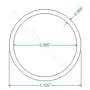
http://flyer.thenetteam.net/3batterygen/magcore.jpg
-
I would be interested in the 1" X 1" rotor magnet build since
these magnets have twice the strength of your 2" X .250.
24 magnets on a 12" rotor? If so that rotor would offer 4X the
flux or better of your thin 2" ones but like you say it depends a lot on
cores too.
Gaps make huge difference I noticed with my 50lb magnets. A 1/4" gap
barely did much. I went to 1/8" then a tiny smaller and wow wee did that
speed up great. I think you use 1/8"Leave a comment:
-
Magnets
I started with 2� x 1/4
Went to 1� x 1/4 but twice as many
Went to 1� x 1/2
Went to 1� x 3/4
Went to 1� x 1
Went to 3/4 x 1� but more magnets on rotor.
Decided 3/4 was minimum diameter I wanted to try.Leave a comment:
-
Magnets strenghthOriginally posted by Turion View Post
2" X .250 = 50lb
1" X .250 =25lb
1" X .500 =50lb
1" X 1" =100lb
1" X 2" =200lb
Roughly, give or take generalization, I know you have .250 so is this
the thickness you normally used in your smaller magnet tests or were
some of them thicker? My 1/2" X 1" = 50lb
I think core dia is 3/4" right? or are you using 1"? Maybe you tried 2"
but that depends on material.Leave a comment:
-
Magnet mass
The mass of the magnet determines the flux created in the coil. But every coil has a limit to how much flux it is capable of accepting during the time of the magnet pass. Whether a two inch thick magnet will create more flux than a 3/4 inch thick magnet is yet to be determined. So FAR I have tried 1/4, 1/2, 3/4, and 1” thick magnets. With each version I got more output. I made the decision to skip a few steps and go straight to a 2” magnet, and would have gone to 3" if I could find rotor material thick enough. There is a chance there will be no more flux that with a 1” magnet and I will have wasted my money. Since this is the LAST version of this generator I am building I made the decision to take that risk. Folks can do what they want. And based on past performance, nobody is going to build a replication anyway. The one thing I was hoping to see was being able to increase the speed without reducing the output. Because iron cn only fill at a certain rate, you are in danger of passing the core before it has absorbed the magnet flux from the passing magnet, so there are lots of things to be tested with this machine. As I have stated before, it works, but it may not be Army material yet ("Be all you can be")Last edited by Turion; 06-25-2019, 11:56 PM.Leave a comment:
-
Bi gets a star on his forehead and not sent to the office, Right?
Bi you are being goated into going off the handle as you love
so well.
What are you talking about, round and square , thick and thin.
What about speed up? Did you do a coil that speeds up?
Leave a comment:
-
Mind sight?
Simple. Why don't you see long bar magnets used in commercial generators and motors? What attribute is enhanced by using a 3/4dia x 3" long magnet over the 3/4dia x 2" long, or 1" long magnet?Originally posted by Pot head View Post
Turion said a few weeks ago it was the magnet mass which matters. Sometimes that is true (certainly in the price). But not so much for the attributes (flux, force, etc) in all cases. Maybe for a 3/4" dia magnet going from 1/8 to 1/4" thick makes a big difference. But 3" thick?
But then I have no idea why he chose that.
biLeave a comment:
-
Most interesting thought, please explain your mind sight as you are seeing it in action.
Thanks bistander.Leave a comment:
-
Magnet d vs L
You rarely see (don't know if I ever have) generator or motor magnets with thickness greater than the sq rt of face area, or in this case, length greater than diameter. I'm not sure what you use for design criteria, but if you run through this calculator for flux or pull force, or repelling force, for various thickness (L) values, you can figure point of diminishing returns, or in other words, paying for PM volume which doesn't do anything good.
https://www.kjmagnetics.com/calculator.repel.asp
Also, in that diagram, the .5 dia x .25" thick magnet in the middle will serve better if it were iron or steel.
biLeave a comment:
-
Cool little machine, so compact and lets see 36vdc X 18amps = 650wattOriginally posted by Turion View Post
approx. You could run six 100watt bulbs right Bi? A principle?
No wonder I been feeling like I am being sent to the office so many
times. the principles office is the scary place
All seriousness set aside I think you standing in front of that
rotor without a guard has me on pins and nettles over here. I guess
you were right about mistakes but it is lots of fun to watch your
early stuff. What people don't know cause they ain't old as us is
how Tesla books were around in the 60's when we were kids and this
is when they all went in the dumpster at our school. Even as a boy I
had the smarts to go out back and dig those books out.
They painted Nick to be a mental maniac in the newspapers with
drawings of electrical probes sticking out of peoples heads as a
health cure. During the mid to late 1900's there was so much
conflict with the subjects he wrote about. I went to the principles
office and asked if the Tesla books would be replaced that were
pitched in the trash. He said no, that these subjects were outdated.
I was 14years. I was sad about it. I would spend long hours reading
those books learning the material and then nothing replaced it. In
later years starting from 14 whenever i went to a school library or
a college library I never found a single Tesla book. Still to this day
I am in disbelief.
Thank you for these special video's based on Tesla's work that has
always been dear to my heart.
Yes quite significant that the neutralization magnets have cut down
the amp draw to less than half of 648watts.
I am a firm believer in the neutralization part. All North's for me.
Leave a comment:
-
Videos
I am going back and finding old videos on my phone to post to YouTube. NONE of them were made to give out information. None were made to share with YOU. Most were made to share specific things with Matt or with my machinist about issues as we developed the generator. Some of the videos show inputs, and some show outputs. Some may show BOTH. Remember, as I begin posting these, they are EARLIER versions of the generator. Many were BEFORE I figured out speed up under load or magnetic neutralization.
You will see many, MANY mistakes as I learn what things like amps and volts are, and how to really measure them. Remember, I was a school principal for crying out loud! The only electricity I knew how to work with was AC, and only enough about circuits to wire a house without getting myself killed. You will see me measuring the AC output of the coils with the meter set on DC. You will see me trying to measure amps with no load, or whatever. Am I embarrassed? Nah. Too old for that crap. I make mistakes. I move on. I try to give you the truth as I know it. AM I always correct? NO. But what fun would it be if I was always right? Then bi would have nothing to complain about!
https://youtu.be/l4Rjh0w3SuY
https://youtu.be/K-ofPZCBUak
https://youtu.be/ZwfcVr4dWOc
The next video I am about to post shows the machine running on 36 volts and drawing 18 amps with only HALF the coils in place. It is SIGNIFICANT that I can now run the same motor on 24 volts at 12 amps with ALL TWELVE coils in place, don't you think????
https://youtu.be/A3DakXN-cR8Last edited by Turion; 06-25-2019, 05:31 AM.Leave a comment:
-
Here is an example of the magnet covers I use to make them impactOriginally posted by Turion View Post
resistant. This is the thickness I use and here are the benefits.
$5 per foot
https://mysteelyard.com/product_info...ducts_id=11274
negligible as far as space is concerned. Once in all side projecting
fields are pushed out front where we want it. There are some examples
on youtube where magnet rotors having upperwards of 20 have shields
and magnets4less only has a cheap refrigerator magnet junk pile.
Once pressed in you can and should leave a few thousandths sticking
out then the outer surface of the shield can be wildly ground rough tp
a point of distortion to receive a greater epoxy contact and holding
power. Much better. What is even more important for your application
is that the magnets all having shields would increase the holding power
probably 50%
The most important use is when you want magnets close together so
their fields are out front and not over lapping. It is a harder task that
you may be tempted to stay away from even though it might produce
double the output.
here is what I know, when bring a block of steel near my shield-less
magnets at the bloch wall they spin around and snap right on at a
distance of 1/4".
With shield the same block of steel has no effect and does not respond.
No magnetic pull sitting right on the bloch wall, nothing, it's all out
front and man is it ever strong where it is suppose to be.
 Last edited by BroMikey; 06-25-2019, 03:32 AM.
Leave a comment:
-
I wish the video had analog meters to show the actual voltages before, during and after.Leave a comment:
-
Reposting Video
I am reposting this video to emphasize a point. When you are running the modified motor on the three battery system, I have said the SIZE of the battery makes a difference. In this video I show two batteries in series charging batteries. If I had only charged one or two batteries, the gain would have been about the same per battery, because of battery impedance in the small batteries, but because I had a LARGE NUMBER of them, I was able to spread the charge energy across ALL of them. That is why I said you need a large deep cycle battery. Because you PAY for the energy (it is pulled out of the two primary batteries) that is used to run the motor and it is going to use the same amount of energy whether you charge ONE high impedance battery or 30 of them. As I showed, you can charge a BUNCH because there energy is THERE, but a single battery can only absorb so much per rotation of the motor. The rest basically goes to ground. You need to think differently if you are going to be successful with this stuff.
https://youtu.be/VMxEUZfncvA
DaveLeave a comment:
-
Info
Bro Mikey,
Attached is a way to make SURE the magnets do NOT come out of the rotor. In the 41/4” thick material you drill in two inches deep and 3/4 wide from each side. This leaves you 1/4 thick material in the center 3/4 diameter. You drill a 1/2” diameter hole in that material and fill it with a 1/4 thick by 1/2 diameter magnet. This acts as a magnetic link between the two larger magnets. Good luck getting them out!
Also attached is a picture of arotor with magnet centers at rotor centers. This is what needs to happen to fit the construction of the coil holder from the size materials I have shown. As you can see, there is plenty of room between magnets. There needs to be at least a magnet width between magnets , and I have more than that. But I also have only 12 (on each side) magnets on the rotor. I have room for more, so I am going to look at that.
Have you built a rotor WITH iron shielding and one WITHOUT iron shielding around the rotor magnets to measure the difference in coil output? I ask because adding iron shielding basically increased the diameter of the rotor magnet which means you can have FEWER magnets on the rotor. If there IS a gain from using magnetic shielding it is going to be x amount per magnet pass times a number of magnets vs a smaller output times a larger number of magnets. Which gives the most output? I don’t know. I really can’t afford to build two rotors to compare the difference.
Also, it doesn’t have to be 24 magnets or 12 magnets. It can be any even numbered amount.Last edited by Turion; 06-24-2019, 02:59 PM.Leave a comment:
Leave a comment: