-
Half of the Answer is knowing the right Question -
Dave45,
Awesome video, looks promising. The input looks to be
pulsed DC. The following looks to be either a support
base allowing it to stand, or some kind of third coil.
Any additional info on this?
Here's another video, using a Bi-Toroid frame.
Its a bench test of the famed arrangement, with
a mysterious result.
[ Bitoroid BiTT Transformer - Unsolved Mystery - ]Comment
-
Bi-Toroid Transformer
Interesting concept.
Thanks for your post.Last edited by vidbid; 02-01-2012, 04:08 AM.Regards,
VIDBIDComment
-
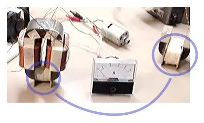
Besides the input to my primary coil being pulsed DC, does my system
seem to be on the right track? My goal with it was to use the
thickness of the cores to prevent the bEMF from reaching the primary
while keeping the permeability of the materials at a level conducive
to producing lots of output.
Otherwise it has become a matter of expense and little availability
in finding the correct core parts to build a working system with
dual-reluctance materials.
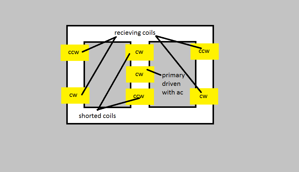
My guess is ideally the transformer might be constructed from four
U-shaped ferrite cores and a thin primary, by comparison to my
current system with the extraordinary amount of .03 mig wire
accounting for the decoupling pathways.Comment
-
I believe its a third coilOriginally posted by geotron View Post
Your doing some interesting work, great vid, what are you using for a core, Im haveing the same problem finding core material,
I went yesterday and bought some three quarter weld grade round stock, would rather have ferrite or metglas but we do what we can.
daveHalf of the Answer is knowing the right QuestionComment
-
Just an idea I want to try
 Half of the Answer is knowing the right Question
Comment
-
Dave45,
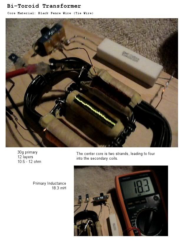
The core materials I've used are ferrite and er70s mig welding wire.
In woopyjump's version of the BiTT, the output is enough that it
will power lightbulbs.
[ BiTT Power Factor 3 by woopyjump ]
---------------------------------------------------------
The input to the primary of the DC-pulsed BiTT from my video was at
roughly 1.25V through 20ohms or 78mW, while the output was at 144mV or 1mW.
When driving the primary with the following resonator circuit there
was an input of 12.5V and 96mA or 1.2W, while the output being 600mV
on a 20ohm was .018 Watts.
[ Video: Bi-Toroid Transformer Resonating ]Last edited by geotron; 02-02-2012, 08:48 AM.Comment
-
Output Examination
The following video will show running values from the same
transformer as in the other two I've posted, only this time
the meters are connected directly through the primary and
secondary coils to measure AC while a 47nF capacitor is
turned on and off from the circuit. The resonation of energy
with a capacitor seems to produce a desireable effect on the
output, running from a 12V laptop adapter.
I've omitted the mig-wire decoupling cores due to their
apparent non-functionality. They will actually decrease
the output values once in place.
[ Transformer Output Experiment ]
Comment
-
Black Wire BiTT
[ Performance Video ]
Primary: .9ohm, 3 layers 25g
Secondary 1: 1.7ohm, 3.57mH, 5 layers 25g
Secondary 2: 1.8ohm, 4.14mH, 5 layers 25g
Variac used with 120VAC outlet.
Results show,
10ohm resistor into primary reads ~ 2.165 VAC
Loading the secondaries does not seem to effect it.
20ohm output resistor reads .065 VAC when both
secondary coils are connected and .063 VAC with one.
Obviously these figures do not represent the correct outcome,
and I'd like to question why this is so. Upon viewing
woopyjump's favorable demonstration of his black wire BiTT,
the only noticeable difference seems to be the much
greater impedance of his primary.
Would then increasing the impedance of my primary coil cause
a resultant leap in output? Have I mistakenly used the wrong
type of black wire? What else could be going wrong?
Comment
-
-
A 3d BiTT could be build using off the shelves transformer cores. I've seen a similar design before but you could use 3 identical toroidal transformer cores to do the job. They could be silicon steel, nanoperm, metglass...toroids or a combination of them. All experiment I saw deal with mW ranges surely that could be scaled up?Last edited by broli; 02-13-2012, 11:39 AM.Comment
-
2D/3D BiTT & Rings BiTT
I think that 3D design would work when comparing essentially the same thing in 2D.Originally posted by broli View Post

It's basically two small rings inside one large ring.

I wonder if the rings couldn't be built out of iron wire.
Regards,
VidbidLast edited by vidbid; 02-14-2012, 06:52 AM.Regards,
VIDBIDComment
-
I'm talking about high power outputs something which needs some decent bulky efficient power transformer cores to achieve. As far as I can tell I haven't seen any kW Bitt's before.Originally posted by vidbid View PostComment
-
Yep. I was interested in the coil configuration.Regards,
VIDBIDComment
-
The tri-toroid configuration looks workable... as for this
black wire version, it's ability to transfer magnetic flux
seems to be lacking in a big way.
The following is my report after rewinding the primary. Having
used masking tape between the layers, an inadvertant connection
has left it a bit darkened from heat. Thankfully caught in time
to avoid producing flames, the coil has shown to be resilient.
After connecting it through a variac it has shown to have
better performance than the previous one, although does not
yet look to produce a gain in energy.
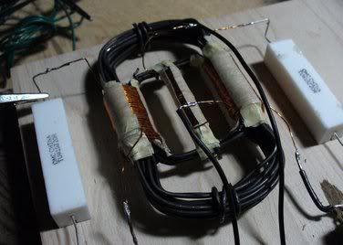
The primary core of two wires is secured to the inner toroid
of four wires by bending each sideways and then wrapping around
it with another wire. This method may be partially responsible
for the transfer performance, versus having one continuous
pathway from the primary core into each secondary coil.
It would have been extraordinary to wind this primary coil
in place between the two secondaries with the mass of wire
that it took.
Perhaps spot-welding it would improve things a little... ?
Comment
 Tweet
Tweet
") It looks as though my question has already been
It looks as though my question has already been 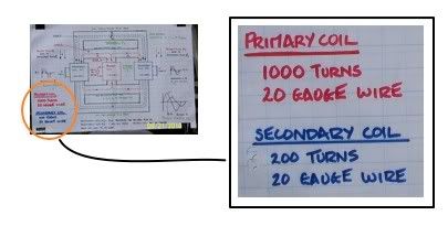
Comment