Announcement

Collapse
No announcement yet.

Lockridge Device - Peter Lindemann

Collapse
X
 
  • Filter
  • Time
  • Show
Clear All
new posts

  • This quote is from the ozone.bz website:
    "A no back emf motor with recovery of that field..."

    Is this the fabled "Having no cake and eating it too?"
    “Advances are made by answering questions. Discoveries are made by questioning answers.”
    —Bernhard Haisch, Astrophysicist

    Comment


    • Looked like a post-&-run, doubt he'll be back...

      Give him a piece of your mind directly instead:

      GoReggie = Reginald Garcia
      YouTube - goreggie100's Channel
      "Electric Motor Company (of) America":
      http://www.EMCoAmerica.com/Contacts.html
      951-300-3371 = Sprint/NexTel cell phone
      Telephone Number IDentification - Searching
      GoReggie2@Verizon.net

      He is also listed as a "Manager" for fire alarm services here:
      "TDC Communications":
      Contact Us
      CCTV Security TDS
      1701 Rimpau Ave Suite 101
      Corona, California
      92881-xxxx
      909-217-4376 - Tel
      951-625-5476 - Fax
      TDCComm1@Yahoo.com
      T.Chacon@TACI.tv

      Also listed as a "Government Vendor" here:
      "Renaissance Structures"
      http://www.Government-Vendor.us/Comp...dale/Home.html
      26365 Buccaneer Lane
      Helendale, California
      92342-2051
      951-300-3371

      Hope this helps somehow.
      Attached Files

      Comment


      • I think somehow he thought he could pull it off.

        You can only thank stupid people, they set the bottom of the bar for everybody else.

        Matt

        Comment


        • Deleted off topic drivel...
          Last edited by WeThePeople; 04-22-2011, 09:24 AM.

          Comment


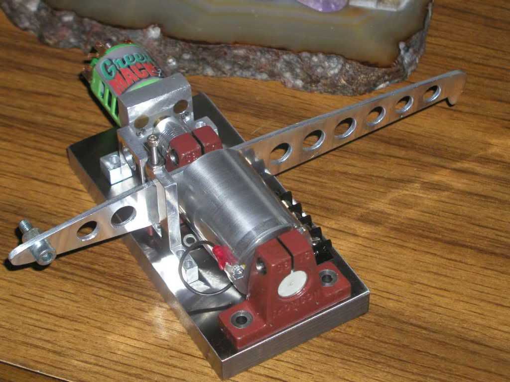
          • The first dyno was damaged and had enough design problems that it was not worth repairing. This is my second attempt at an improved dyno.

            Base is steel
            Absorber is brushless
            Absorber bearings are full ceramic
            All other bearings are hybrids
            No shims
            Only one drive shaft to connect test motor to coupler
            Total drag with synthetic lube in all five bearings is much less than first dyno
            Electronics are the same except the bridge added for the new absorber

            I estimate this dyno will easily handle shaft speeds in the 30-40,000 RPM range and should allow measurements to 150 Watts.

            Comment


            • Some help please.

              After several attempts at different windings, I must declare that I am beaten.

              My setup is similar to that which Turion showed a few pages back and that
              which Brian (n84dafun) shows.

              Razor scooter B1308222 motor

              2 pole
              12 segments
              12 slots

              I now understand why I get 1 pulse at 0 degress and a reverse pulse at 180.
              Hence, no continued motion.

              I tried the diode, but no joy.

              I clearly see the z-type winding for Matt's 4 pole setup, though I cannot see
              how to apply this to the two pole with 12 slots.

              I will keep going while the skin on my fingers holds up, but would greatly appreciate any advice.

              Kindest Regards, Penno
              Last edited by penno64; 04-22-2011, 08:33 AM.

              Comment


              • Originally posted by joeqsmith View Post
                The first dyno was damaged and had enough design problems that it was not worth repairing. This is my second attempt at an improved dyno.......
                Thats some pretty work. Looking forward to seeing your results.

                Originally posted by penno64 View Post
                Some help please.
                After several attempts at different windings, I must declare that I am beaten.
                My setup is similar to that which Turion showed a few pages back and that
                which Brian (n84dafun) shows.
                Razor scooter B1308222 motor
                2 pole
                12 segments
                12 slots
                I now understand why I get 1 pulse at 0 degress and a reverse pulse at 180.
                Hence, no continued motion.
                I tried the diode, but no joy.
                I clearly see the z-type winding for Matt's 4 pole setup, though I cannot see
                how to apply this to the two pole with 12 slots.
                I will keep going while the skin on my fingers holds up, but would greatly appreciate any advice.
                Kindest Regards, Penno
                What happened with the diode? How many magnets in the motor?

                If you have 2 magnets.....
                Your winding should start on the same side as the commutator go through slot 1 and down to 6, and back up to one.
                looking at the rotor from the commutator you should use 2 slot of the commutator to left of the wire slot.
                Your motor will be a puller if wound this way.

                If you need a drawing ask. But give all the specifics of the motor you have, or link to the one your talking about.

                Cheers
                Matt

                Comment


                • Hi Matt,

                  Thanks for the reply.

                  Yes it a 2 pole (2 magnet) motor.

                  I have soldered the diode in the other way, but still no run.

                  I added some weight and found that it will run - just!.

                  And yes, I had it wound as you detailed.

                  Matt, from Peter's comment regarding your Z-type wind, I feel we need a different way of winding for the 2 magnet motor.

                  Using Brian's offset brush placement, means I can eliminate the internal diode, so
                  I will need to do some work on the brush holder.

                  Once again, Thanks for the advice.

                  I will post a couple of Pics if time permits.

                  Kindest Regards, Penno

                  Comment


                  • Here's a few pics.

                    The magnet rotor was simply used as flywheel.

                    Thanks
                    Attached Files

                    Comment


                    • Hi Penno64

                      With the 2 pole motor your using there is no way to wind a zig-zag style, that is for a 4 pole motor.

                      With the 2 pole motor you also dont need a diode. With a diode your motor will only fire 1 time per revolution. Without the diode it will fire twice per revolution.

                      You may also want to hook 2 commutator sections together where your coil wires are hooked up so you can have a longer "on" time. This will get that motor really going.

                      I also did not see any recovery brushes in your pictures. Without the recovery brushes you will have lots of arcing and will burn up your power brushes quickly.

                      I'm not sure how many volts you used to run your motor but you also need to increase the voltage, remember that the way your motor is now with only 1 pulse per revolution and only using 1 commutator section you have an effective on time of only 8-9%.

                      Comment


                      • Matt and Mark,

                        Thanks so much for the advice.

                        She, who must be obeyed, is dragging me out for a 4 day Holiday.

                        I'll be back, then test your suggestions.

                        Kindest Reagrds, Penno

                        Comment


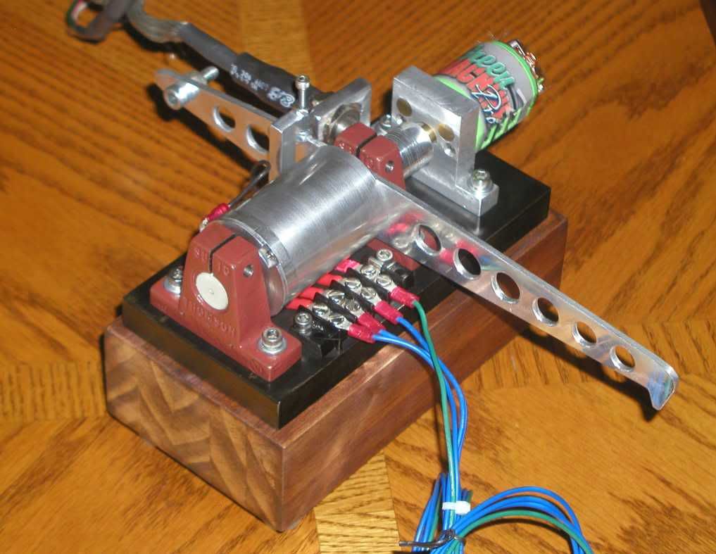
                        • Completed dynamometer.

                          Comment


                          • Dyno is now complete. Here is a video of the Green Machine motor under test. About 80 Watts of output power, 50% efficient.

                            YouTube - Mini-Dynamometer

                            Comment


                            • I've been spending a lot of time researching this motor issue. The brushes are a pain in the butt. I was thinking that what we really need would be a motor with the permanent magnets on the rotor, and the coils on the stator, around the outside. I know this isn't exactly what Peter described to us, but I am wondering if this would significantly affect performance, or even kill it. For the life of me, I don't know WHY it would, but then I'm not the expert, and Peter certainly is. I suppose the magnetic field might have a tremendous amount to do with it.

                              Anyway, I have approached this from two different directions. First, I ordered a brushless 12 volt DC motor from this web site N2311S018

                              It is set up the way I described, with neo magnets on the rotor and windings around the outside on the stator. Just exactly what those windings look like, I don't know. Still looking for specs on that particular motor that will tell me. The link to specs on the motor page doesn't show how the windings go. I want one for some other things I am doing, so if it doesn't pan out for this project, so be it.

                              The second thing I did was take apart a standard car alternator I got from a junkyard and replace the entire rotor with a 3/4', 12" long steel bolt that I had machined down to fit into the bearings at one end, and through the bearing and case at the other end so I would have a shaft to work with. Because there are 42 slots in the stator for windings, I have gone with 3, wound, 11 off 3 wound, 11 off 3 wound, 11 off. The rotor will be triangular with magnets in three locations and it will fire three times per revolution. I drilled a 3/4 hole in some plastic, stuck it on my bench grinder to spin it, so that I could make it perfectly round, and then cut slots in it for magnets. Now I have a rotor with magnets on it for my testing. I'm not finished with it yet, so I will let you all know if it actually works. If not, I only have myself to blame.

                              I DID build a motor exactly the way Peter told us to, and I'm very happy with the way it is performing. I always try to follow directions EXACTLY before I go off and do something different. Just hate those brushes, and wanted to figure out a way to eliminate them. Maybe I'll find that the brushes are critical to performance. Stranger things have been known to happen!
                              Last edited by Turion; 04-28-2011, 11:35 PM.
                              “Advances are made by answering questions. Discoveries are made by questioning answers.”
                              —Bernhard Haisch, Astrophysicist

                              Comment


                              • Hi all,

                                Is this what we are trying to achieve -

                                It WORKSSSSSSSSSSSSSSSSSSSSSSSSSSSSSSSSSSSSSSSSSSSSSS SSS !
                                I am going to upload the video, is almost 20 minutes of self running.
                                The skeptics should prepare the arsenal.....


                                YouTube - Muller Generator - self running - Test1


                                Romero from the UK has demonstrated it and is now assisting replicators

                                Would love to here Peter's comments and how we may adapt this to work
                                in our Lockridge.

                                Kindest Regards, Penno

                                Comment

                                Working...
                                X