 Tweet
Tweet
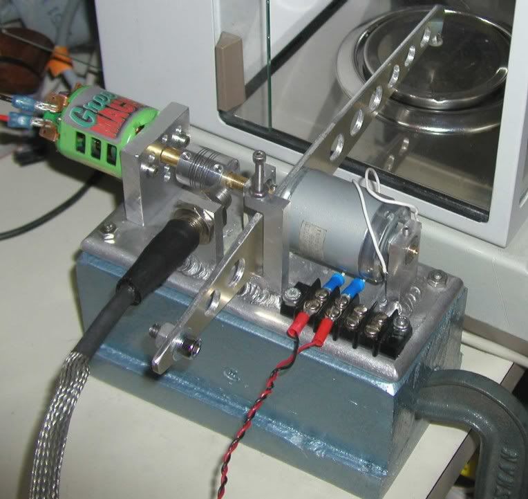
My small dynamometer with a range of less than 2 mNm to over 110mNm.
This dynamometer uses a small DC motor to act as the absorber. The motor to be tested is mechanically linked to the absorber by a series of driveshafts and a coupler. The absorber is mounted in such a way that it is allowed to rotate. An arm is then mounted to the absorber. As load it added to the absorber, torque is created in the arm. The arm pushes downward on a precision balance. A hall type sensor is use to measure the shaft rotation. A computer is then used to control and monitor the dynamometer as well as display the data.
Wiki is a good source if you would like more details about how a dyno like this works.
Dynamometer - Wikipedia, the free encyclopedia
The following shows the two support bearings for the absorber along with the coupler. The coupler will have two small magnets mounted inside.
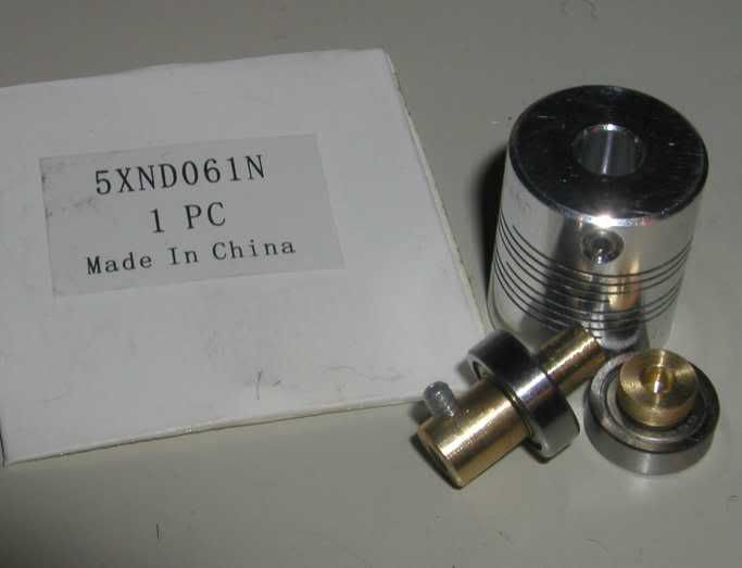
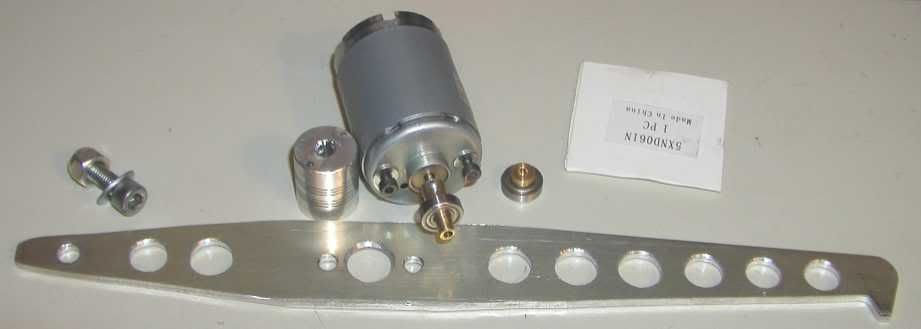
The torque arm, modified coupler with magnets, absorber and the counter balance for the arm.
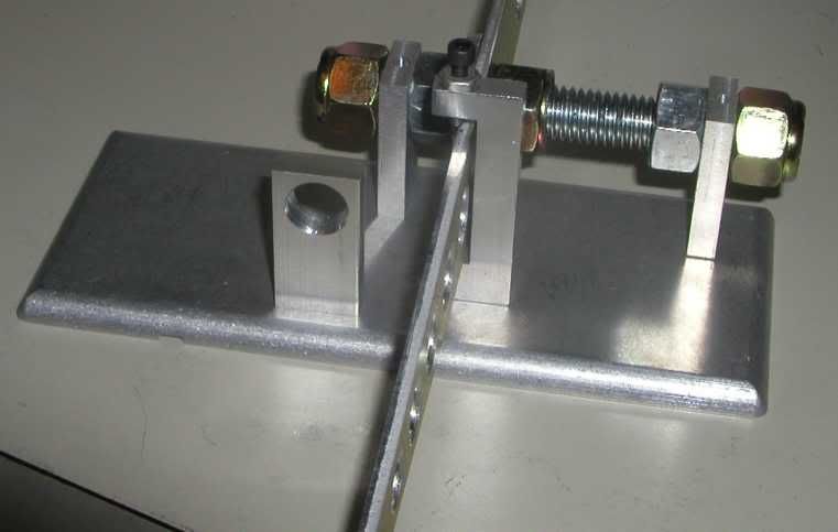
The base with the bearing supports, torque arm limiter and hall sensor mount. The threaded rod holds the bearing supports in place for welding. The bearing holes are undersized and line bored after welding.
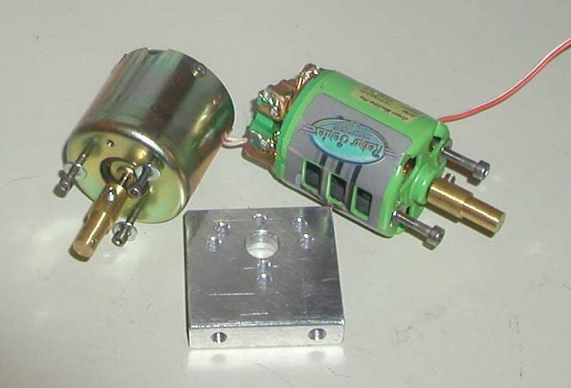
These are two of the motors I plan to use to test the dynamometer along with the motor mount. The mount was not welded to the base to allow ease of motor change out. The motor on the left is from a VCR and was used to drive the tape spindle. It is rated for 6V operation and has very low torque. On the right is a hobby motor. It has much higher torque and capable of running at 20,000 RPM.
The dynamometer and balance with the hobby motor installed.
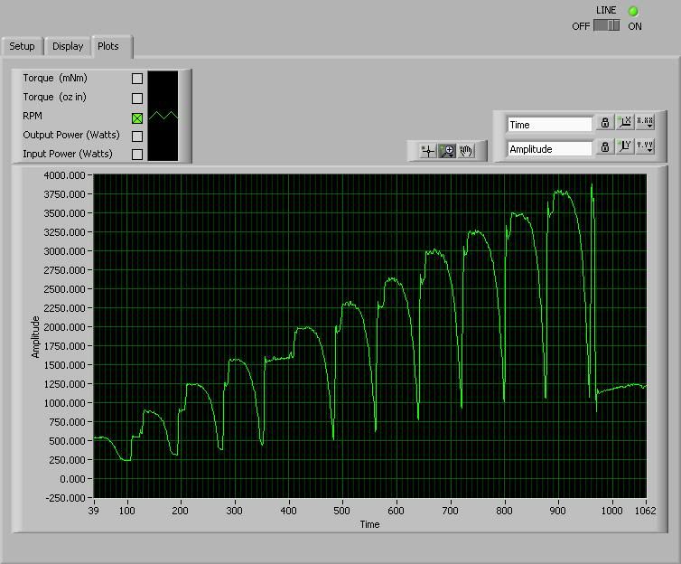
Looking at pulls with the 6V VCR motor. RPM is shown. Motor supply voltage was set to 4V then incremented in 1V steps to 14V.
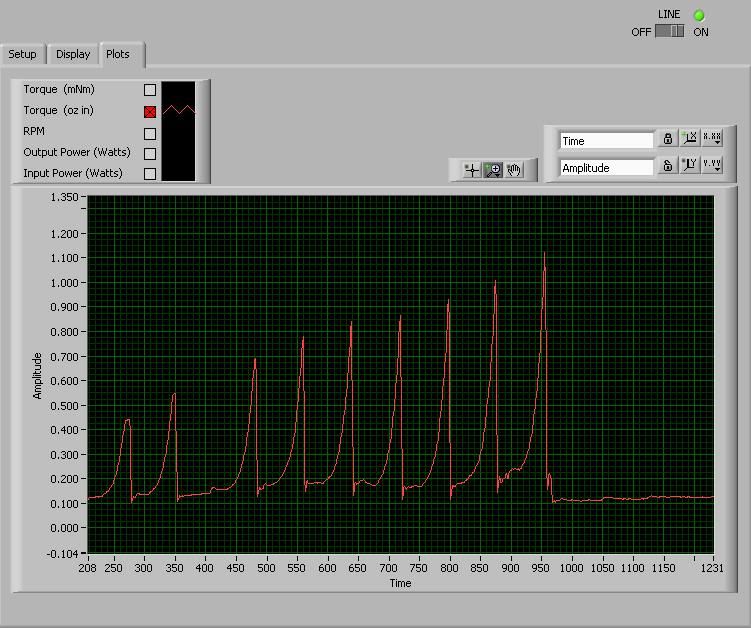
Looking at torque for the same pulls.
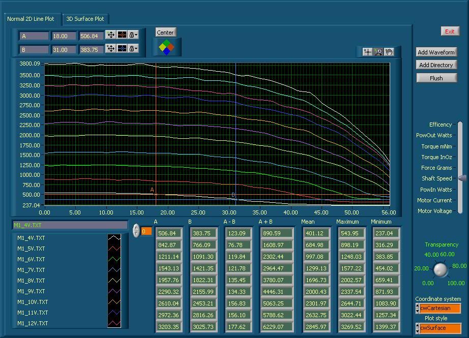
Here the data is overlaid to show each pull. Notice that the shaft speed increases at the end of each consecutive run as the voltage increase. The system is not yet closed loop.
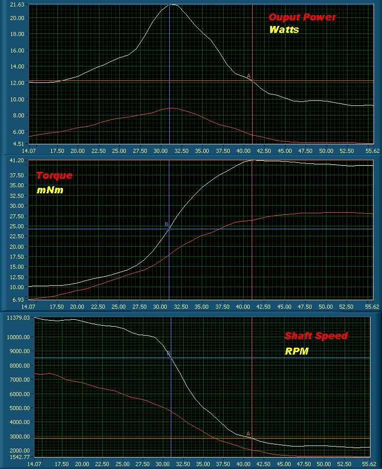
Showing motor output power in Watts for all 11 pulls.
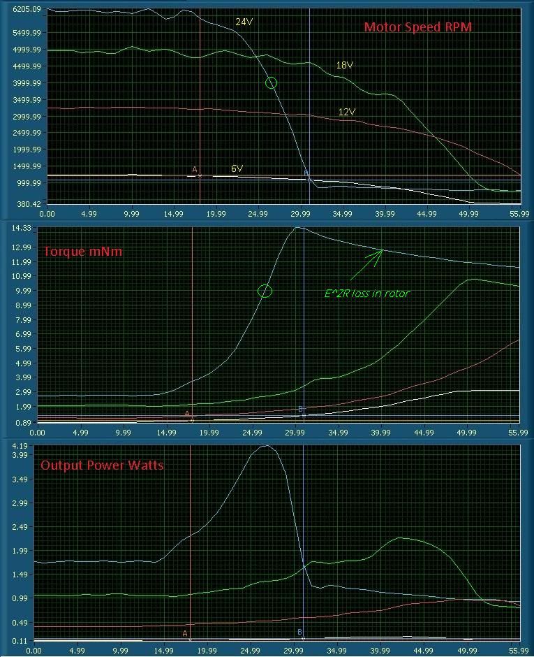
The 6V VCR motor was ran again at 6, 12, 18 and 24V. The following set of plots show the effects on the speed, torque and output power.
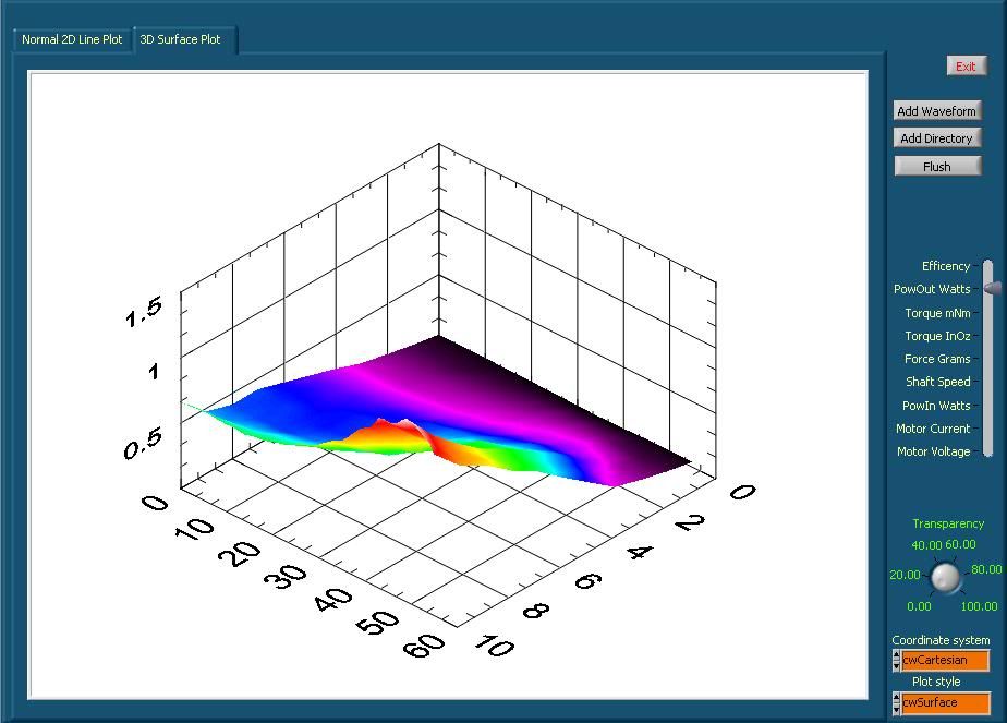
This data was taken from the green hobby motor. The ratio of output to input power shows that the motor is most efficient in the area left of the peak output power. This matches with the manufactures data. Currently I have not pushed this motor to its limits because of the vibration at these higher shaft speeds.
If your considering building your own dynamometer, I have created a list of my concerns with this setup.
1) Pick a better absorber, or make one from scratch. The rear support is just not stable enough. I had some ideas on what I wanted to measure so I sorted motors to find something in this range. The motor's bearings, the fact it has brushes, balance, etc all make this a bad idea. Designing something to do the job right would be better time spent.
2) Use better construction practices. While I knew the aluminum would warp during welding, I had left the bearing holes 10 under. After welding, I then borded them with a reamer. This is fine, but the small amount of warp in the base causes drag when it is clamped to a flat surface. IMO, don't weld. Machine the bearing support from one piece and then bolt it to the base.
3) Use C -clips to hold the bearings. The setscrews cause the bearings to distort and add drag. It does not take much.
4) Make sure that the bearings you use are up to the task. This dyno was made from scraps. This included the bearings that came from a small stepper motor I had tore apart. This was a poor choice.
5) With a 6" torque arm, make sure the shafts are near perfect. Any errors here are just multiplied by the arm length.
6) Figure out a way to balance the rotating parts. I have some ideas, but nothing proven.
7) I had tried to keep the rotating weight down. A flywheel may help to reduce vibrations.
8) The coil type of coupler I used may not be the best choice. Any missalinment adds drag.
9) Design a better mount for the test motor. The block is OK, but imagine drilling holes for all your motors. Maybe something with micrometers to fine tune the XY&Z.
10) Think about adding a closed loop control system. This system would have it, but I think it has enough problems that it does not warrent any more time spent on it.
11) The power supplies compensation lines need to be connected to the motor and the cable sizes need to be increased.
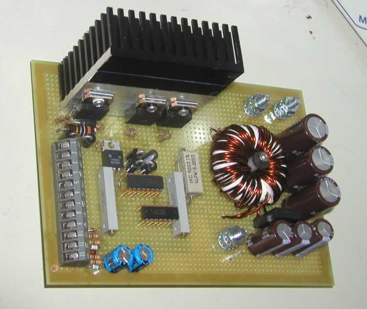
12) Use a larger heat sink for the absorber's FET drive.
13) Come up with some sort of air duct system for the motor and absorber as well.
This dynamometer uses a small DC motor to act as the absorber. The motor to be tested is mechanically linked to the absorber by a series of driveshafts and a coupler. The absorber is mounted in such a way that it is allowed to rotate. An arm is then mounted to the absorber. As load it added to the absorber, torque is created in the arm. The arm pushes downward on a precision balance. A hall type sensor is use to measure the shaft rotation. A computer is then used to control and monitor the dynamometer as well as display the data.
Wiki is a good source if you would like more details about how a dyno like this works.
Dynamometer - Wikipedia, the free encyclopedia
The following shows the two support bearings for the absorber along with the coupler. The coupler will have two small magnets mounted inside.
The torque arm, modified coupler with magnets, absorber and the counter balance for the arm.
The base with the bearing supports, torque arm limiter and hall sensor mount. The threaded rod holds the bearing supports in place for welding. The bearing holes are undersized and line bored after welding.
These are two of the motors I plan to use to test the dynamometer along with the motor mount. The mount was not welded to the base to allow ease of motor change out. The motor on the left is from a VCR and was used to drive the tape spindle. It is rated for 6V operation and has very low torque. On the right is a hobby motor. It has much higher torque and capable of running at 20,000 RPM.
The dynamometer and balance with the hobby motor installed.
Looking at pulls with the 6V VCR motor. RPM is shown. Motor supply voltage was set to 4V then incremented in 1V steps to 14V.
Looking at torque for the same pulls.
Here the data is overlaid to show each pull. Notice that the shaft speed increases at the end of each consecutive run as the voltage increase. The system is not yet closed loop.
Showing motor output power in Watts for all 11 pulls.
The 6V VCR motor was ran again at 6, 12, 18 and 24V. The following set of plots show the effects on the speed, torque and output power.
This data was taken from the green hobby motor. The ratio of output to input power shows that the motor is most efficient in the area left of the peak output power. This matches with the manufactures data. Currently I have not pushed this motor to its limits because of the vibration at these higher shaft speeds.
If your considering building your own dynamometer, I have created a list of my concerns with this setup.
1) Pick a better absorber, or make one from scratch. The rear support is just not stable enough. I had some ideas on what I wanted to measure so I sorted motors to find something in this range. The motor's bearings, the fact it has brushes, balance, etc all make this a bad idea. Designing something to do the job right would be better time spent.
2) Use better construction practices. While I knew the aluminum would warp during welding, I had left the bearing holes 10 under. After welding, I then borded them with a reamer. This is fine, but the small amount of warp in the base causes drag when it is clamped to a flat surface. IMO, don't weld. Machine the bearing support from one piece and then bolt it to the base.
3) Use C -clips to hold the bearings. The setscrews cause the bearings to distort and add drag. It does not take much.
4) Make sure that the bearings you use are up to the task. This dyno was made from scraps. This included the bearings that came from a small stepper motor I had tore apart. This was a poor choice.
5) With a 6" torque arm, make sure the shafts are near perfect. Any errors here are just multiplied by the arm length.
6) Figure out a way to balance the rotating parts. I have some ideas, but nothing proven.
7) I had tried to keep the rotating weight down. A flywheel may help to reduce vibrations.
8) The coil type of coupler I used may not be the best choice. Any missalinment adds drag.
9) Design a better mount for the test motor. The block is OK, but imagine drilling holes for all your motors. Maybe something with micrometers to fine tune the XY&Z.
10) Think about adding a closed loop control system. This system would have it, but I think it has enough problems that it does not warrent any more time spent on it.
11) The power supplies compensation lines need to be connected to the motor and the cable sizes need to be increased.
12) Use a larger heat sink for the absorber's FET drive.
13) Come up with some sort of air duct system for the motor and absorber as well.
 . I will take some pics in a few and add them. I still need to clean up the brushes as the run brushes have some burning and pitting. Also should I put a second coil on the motor or run just one? Peace
Comment