Announcement

Collapse
No announcement yet.

Lockridge Device - Peter Lindemann

Collapse
X
 
  • Filter
  • Time
  • Show
Clear All
new posts

  • d'oh

    Originally posted by Matthew Jones View Post
    PaulT
    When you wound the thing did you put a diode on the end of the windings.
    Matt,

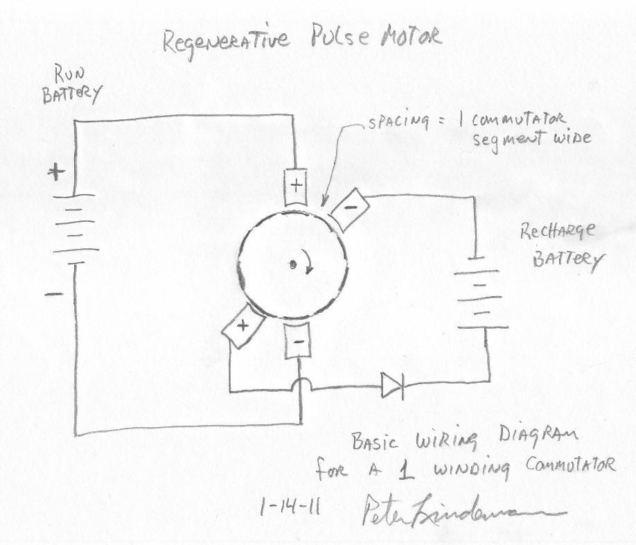
    It turns out that the term "zig-zag" has been used two different ways in this thread. The current usage means a kinda side-saddle winding resulting in two coils like you've got. I have only one coil going through exactly two slots. My setup is like the one Peter originally drew - 1 winding commutator.


    After mulling it over I do understand this scope trace:


    There is no visible spike because it is being smoothed by the attached recharge battery.

    The -8v dip in the top trace (connected directly to the recharge brushes) is BEMF / charge. Just like Peter has been telling us. D'oh. It's only 2ms long because that's how long the recharge brushes are in contact with the coil. I'm still running this at +12V, so -8V of BEMF seems about right.

    When I add a mechanical load and step up the voltage, I should see the % of this BEMF/charge drop relative to the run voltage.

    I'm getting two pulses per revolution, 7ms between pulses * 2 = 14ms per revolution => 71 rps * 60 = 4,286 rpm at 12V with no mechanical load.

    Hmmm, , there are 10 pairs of commutations per revolution, hence 10 units of BEMF. 2 units of BEMF are fighting the energization of the coil. 2 units are being pushed into the wrong end of the diode. 6 units of charge build up(?) in the coil (in 3-unit chunks) and do what? Create counter-magnetic fields inside the motor? Does a 3-unit lump of BEMF come spilling out when the run brushes are contacted?

    If we added 2 more pairs of brushes (a total of 2 run brushes and 6 recharge brushes), or made the recovery brush 3 commutators wide, we could "drain off" the charge (and do something useful with it?). That sounds too mechanically difficult and too expensive for the goals of this thread...

    If I replace the single spike recovery diode with a FWBR, I should be able to capture the spike and send it to the recovery battery plus capture 2 units of BEMF and send that to the recovery battery, also, yes?

    pt

    Comment


    • Originally posted by dragon View Post
      The barbell weight might be a little dangerous. Working with spinning weights it's probably best to spend the extra money and have something made correctly and balanced. The energy stored in a flywheel ( especially at the speeds Matt's little motor is running ) can be quite high and cause a lot of damage if "let free". Those experimenting with "quickie" set ups might want to invest in some kind of entrapment or cage around the flywheel. Far less expensive than a trip to the emergency room.
      That ain't no joke. I thought I was dead for sure yesterday. LOL

      @PaulT
      I gotta read your post a few more time and get my head wrapped around it, then I'll try to answer.

      Matt

      Comment


      • Add: my coil is 0.6 Ohms. That 2ms pulse is I = V/R = 8/0.6 = 4.8A. Will that help or hinder the battery?

        pt

        Comment


        • That won't hurt your battery at all.

          I have not got answer for ya on the other stuff.

          Matt

          Comment


          • Originally posted by Matthew Jones View Post
            That won't hurt your battery at all.
            Interesting. I don't have much experience/intuition with batteries, I guess.
            I have not got answer for ya on the other stuff.
            That's OK. I'm just thinking aloud. If anyone finds something wrong with what I wrote, I'll edit it out or footnote it.

            pt

            Comment


            • re wound

              I re wound the motor trying to get as much in the slot as possible. I am using 22ga. because that's what I have. I impedance matched both to .6 ohms. The motor seems to run a bit slower on 12 volts then before, and I am filling a 25 volt cap to 5 volts in a few seconds. One thing I noticed is that I can run motor either direction and get same output on cap? The recover brushes are spaced one full commutator section apart, there is no overlap from the run brushes to the collector brushes, is this right? Next I need to find some more batteries to get the higher voltage. I am also working on lathing a shaft to install a flywheel, I have one from a treadmill that is about 8" in diameter. Any way, I just wanted to share were I'm at and thank all of you for your progress reports and Peter for helping out so much. More to come later. Peace rawbush

              Comment


              • Originally posted by Robbush View Post
                I re wound the motor trying to get as much in the slot as possible. I am using 22ga. because that's what I have. I impedance matched both to .6 ohms. The motor seems to run a bit slower on 12 volts then before, and I am filling a 25 volt cap to 5 volts in a few seconds. One thing I noticed is that I can run motor either direction and get same output on cap? The recover brushes are spaced one full commutator section apart, there is no overlap from the run brushes to the collector brushes, is this right? Next I need to find some more batteries to get the higher voltage. I am also working on lathing a shaft to install a flywheel, I have one from a treadmill that is about 8" in diameter. Any way, I just wanted to share were I'm at and thank all of you for your progress reports and Peter for helping out so much. More to come later. Peace rawbush
                If you can run the motor in either direction than your timing is not right. You'll need to move where your wires are on the commutators.

                Comment


                • Originally posted by Robbush View Post
                  I re wound the motor trying to get as much in the slot as possible. I am using 22ga. because that's what I have. I impedance matched both to .6 ohms. The motor seems to run a bit slower on 12 volts then before, and I am filling a 25 volt cap to 5 volts in a few seconds. One thing I noticed is that I can run motor either direction and get same output on cap? The recover brushes are spaced one full commutator section apart, there is no overlap from the run brushes to the collector brushes, is this right? Next I need to find some more batteries to get the higher voltage. I am also working on lathing a shaft to install a flywheel, I have one from a treadmill that is about 8" in diameter. Any way, I just wanted to share were I'm at and thank all of you for your progress reports and Peter for helping out so much. More to come later. Peace rawbush
                  What motor are you running?

                  Matt

                  Comment


                  • crude first pronybrake attempt

                    Hi all

                    @ Matt

                    I am with Mark, it so a pleasure to hear you reporting your experiments in a so funny way. Thanks and go on ,but remember we NEED YOU ,so please be carefull.

                    @ all

                    I don't want to disturb here with my one pulse "Hall switched axial fluxed motor", but i have made a video that seems to be in accordance
                    with the searching of this thread.
                    I ,mean that it seems ,that as per my very crude and first prony brake testing , that the torque does not decrease with the increasing speed for the same applied voltage.


                    And it is probably valuable also for the radial brushed motors as MATT and others are using here.

                    ( hope my glasses are not misleading me this time)

                    good luck at all

                    Laurent
                    YouTube - lockridge test 2

                    Comment


                    • The motor I am using was rated for 12volts and 9 amps continuous. It came from a coolant exchange machine. It has a 12 segment rotor and 2 magnetic poles. The slots in the rotor are centered with 12 commutator segments. The timing is set to pulse the coil when it is in center of the two poles, were should the rotor be when pulsed? Also I can only change rotation by flipping the run battery connection.
                      Peace rawbush

                      Comment


                      • some results

                        I installed a 10A panel meter (my mistake was using a fused multimeter, earlier) and got some more batteries.

                        At 12.54V, the ave current is 3.5A (analog meter), 4,285 RPM (calculated from 'scope trace).

                        At 25.5V, the ave current is 4.4A, 7,895 RPM. The -ve pulses on the recovery brushes are about -30V, 0.6-0.8 msec wide. There is certainly a big jolt of current at startup - the meter pinned itself for a moment, then settled back down.

                        @Matt - when you did voltage tests, did you load / slow the motor down or did you let it free run unloaded? I want to be sure that I'm testing correctly, before stepping up the voltage to 36V...

                        pt

                        Comment


                        • One Pulse per Rev - No diode in rotor

                          Here's an image of my write-up of my system. At 36V I was able to get around 6000 rpm at around 1 to 1.5 amps with 3 segments. The resistance of my zig-zag coil was around 1 ohm. I used my oscilloscope to estimate rpm's. I went back down to 2 segments as the write up indicates because my motor got hot after several minutes of running...maybe because I wasn't recovering the spikes through a battery, just left it open.

                          I did notice a slight decrease in speed when I shorted out the recovery leads. I thought the diodes prevented this slow down, maybe because I have the overlap of commutator between the run and recover brush.

                          I should be getting my second motor tomorrow (Mon). It's the same motor so I can compare the two.

                          The disadvantage between this setup and Matt and Mark's is that you have to move the brushes around. However, you don't need diodes in the rotor. I was running my previous setup with two diodes and was getting two pulses per rev, but it had a lot of vibration.

                          Caps on the recovery was above power supply voltage, about 40V with 36V power supply. This setup does not work with my variable power supply, only with my 7.5 Ah batteries.

                          BTW, when I used 1 segment between the brushes, the recovery voltage on the caps are usually below the supply. Maybe because the spikes aren't being captured in time when the disconnect and the reconnect time is even a fraction of a millisecond off. That's why I like the overlap and use two commutators segments.

                          -Brian

                          Last edited by n84dafun; 01-31-2011, 12:35 AM.

                          Comment


                          • Originally posted by Robbush View Post
                            The motor I am using was rated for 12volts and 9 amps continuous. It came from a coolant exchange machine. It has a 12 segment rotor and 2 magnetic poles. The slots in the rotor are centered with 12 commutator segments. The timing is set to pulse the coil when it is in center of the two poles, were should the rotor be when pulsed? Also I can only change rotation by flipping the run battery connection.
                            Peace rawbush
                            You have one coil, wound from slot #1 to #7, right? The run brushes should fire when slots #1 and #7 (containing the coil) are dead center of the magnets.

                            You must be sure that the armature is spinning in a direction such that the run brushes fire, then one commutator later, the recovery brushes engage. There is only one direction for which that happens.

                            Correct, the run brushes should completely disconnect before the recovery brushes connect (with as little time / distance between these events as possible).

                            pt

                            Comment


                            • setup

                              Yes one coil is from slot 1 to slot 7, the second coil is from slot 4 to slot 10. It sounds like the commutation is right, it fires when the coil is in center of the two pole magnets. I plan on adding a degree wheel to the flywheel to record actual settings. Thanks for all the input.
                              rawbush

                              Comment


                              • Hello everyone,
                                I have followed this thead from the start, but have been busy
                                with John B's GT3 replication. But ever since I heard Peter L.
                                at the conference, I have had this hook in my lip. (Ive been caught by the bug,
                                for those who may not understand that.) I even bought what ever DVD
                                he had left there, and watched it on my long flight home.
                                I have these motors that where made by Honeywell back in the 60's.
                                1/2 HP 1200 RPM 12VDC PM motor. I believe the label says 42 amp.
                                I don't see a . in there (4.2??) and they have 28 commutator segments.
                                These where top dog motors back then, and some where re-wound to run
                                at 10VDC. They are a little bigger than a starter motor for a pick-up truck.
                                But they have a long SS shaft to connect a gen. or flywheel.
                                So my question is, will these work for what we are trying here??

                                Mark P.

                                Comment

                                Working...
                                X