Announcement

Collapse
No announcement yet.

Donald Smith Devices too good to be true

Collapse
X
 
  • Filter
  • Time
  • Show
Clear All
new posts

  • Originally posted by radioionics View Post
    Yes, it hit me in the face earlier today, before your post. I have redrawn the circuit to reflect the new upgrade. I appreciate the feedback.

    I don't agree about not using the antenna and ground. They aid in the extraction of energy. Without them the energy is mostly drawn from the HVM, and in doing so the batteries will become depleted, and have to be charged from the grid, generator, or from a solar panel.

    Is there really a need for you to be nasty about the way I reveal the tech to you? Show some appreciation in the fact that I've been willing to share it at all on this forum, please. I wasn't going too but Paul convinced me that it was going to be different this time around. Was he wrong?
    Did not try it yet. Still working nightshift
    The connecting to ground i do not know if that is still correct because of this post. So if we want to know try is both ways to be sure.
    Last edited by Mwtj; 02-10-2017, 04:57 AM.

    Comment


    • Ok! I think we need some guidance. Bruce, can you give some help please?
      It's the night here an I have to go sleep. My brain is boiling. Hope it will be a good night!
      Ciao!

      Comment


      • This circuit takes advantage of natural build up on antenna and attempts to stimulate it. Perhaps working backwards would help illuminate the way. Radio guys ground this buildup to prevent their equipment from being damaged. A search reveals the discharges are high voltage and can be very rapid. In this link the guy discusses how he bleeds the buildup and how frequent the discharges are and the high voltage developed. Antenna Static Charge Bleeder

        al

        Comment


        • When Bruce says the grail is right in front of you he isn't kidding!

          It's so similar to the original mirror circuit schematic you could leave everything in place.

          If someone figures it out we are going to enter the paradigm shift.

          It feels like the Scalar Waves (Radioionics) tutor left you an assignment / puzzle to figure out what scalar waves are, do and behave.

          Bruce, someone called you "old".

          Time to leave the class and retire? Haha

          Comment


          • Originally posted by soundiceuk View Post
            When Bruce says the grail is right in front of you he isn't kidding!

            It's so similar to the original mirror circuit schematic you could leave everything in place.
            Is it also true that we have to only connect one wire between 2 contacts to make it work? And one of these contact is directly connected to the ground??


            Originally posted by soundiceuk View Post
            It feels like the Scalar Waves (Radioionics) tutor left you an assignment / puzzle to figure out what scalar waves are, do and behave.
            Have you some reference document we can read on this.


            Originally posted by soundiceuk View Post
            If someone figures it out we are going to enter the paradigm shift.
            Could you also comment on the theories we made along the road? It will be really appreciated if you guide us; then we could stay on the right track...

            Thank you!

            Comment


            • Here is a picture of my first theorise (Connection of antenna to ground) sorry for the crappy picture.
              I let it run for 15 min.

              Im finally no sure it is it. cause the battery start at 12,35v and finish at 12,02v...
              Attached Files

              Comment


              • Ok, Paul, you like to be funny... Let's look at the timeline of events to date....

                We started with the original release... a dual resonant system with a tuned antenna to provide stationary waves. People started building from this, stated to be the tested and working version.

                Around 12/21 A second drawing appeared before any builds were completed with the first drawing. I studied it a bit and found some inconsistencies with the polarities and mentioned it. Shortly after, the mirror circuit was introduced, which reflected the corrections.

                About now everyone is scrambling to re-build everything they've done to date to match the new circuit.

                2 grounds introduced and the radiant patent BS - I let that go because I wasn't ready to introduce my findings that would show how wrong you really were.

                I then asked why the secondary circuit needed to be resonant... everyone is still working under the premise of standing waves.

                Yet another drawing is introduced, not well thought through as the "basic" build, it wouldn't work at all the way it was drawn and I let that slide which was later brought up by Tswift and corrected at a later date.

                Then out of the blue, tuning is no longer necessary because now it's operating on Scalar waves.

                There is a lot more I could point out within that time line but I'll leave the intricate details for others to decide on their own. It seems to me your throwing krap on the wall to see what sticks...

                I will retire from the academy of "cat n mouse" .

                I sit with bib, knife and fork ready and willing to dine humbly and gracefully on crow upon the arrival of any graduate's.

                I've grown to enjoy and respect the communications between members on this forum and I truly hope I am the one eating crow.... good luck to you all...

                Comment


                • Originally posted by dragon View Post
                  Ok, Paul, you like to be funny... Let's look at the timeline of events to date....

                  We started with the original release... a dual resonant system with a tuned antenna to provide stationary waves. People started building from this, stated to be the tested and working version.

                  Around 12/21 A second drawing appeared before any builds were completed with the first drawing. I studied it a bit and found some inconsistencies with the polarities and mentioned it. Shortly after, the mirror circuit was introduced, which reflected the corrections.

                  About now everyone is scrambling to re-build everything they've done to date to match the new circuit.

                  2 grounds introduced and the radiant patent BS - I let that go because I wasn't ready to introduce my findings that would show how wrong you really were.

                  I then asked why the secondary circuit needed to be resonant... everyone is still working under the premise of standing waves.

                  Yet another drawing is introduced, not well thought through as the "basic" build, it wouldn't work at all the way it was drawn and I let that slide which was later brought up by Tswift and corrected at a later date.

                  Then out of the blue, tuning is no longer necessary because now it's operating on Scalar waves.

                  There is a lot more I could point out within that time line but I'll leave the intricate details for others to decide on their own. It seems to me your throwing krap on the wall to see what sticks...

                  I will retire from the academy of "cat n mouse" .

                  I sit with bib, knife and fork ready and willing to dine humbly and gracefully on crow upon the arrival of any graduate's.

                  I've grown to enjoy and respect the communications between members on this forum and I truly hope I am the one eating crow.... good luck to you all...
                  I understand your decision...
                  Thank you for the input you give.
                  Respect.

                  Comment


                  • Originally posted by radioionics View Post

                    * This circuit has not been tested.
                    Battery pack shown in wrong polarity.

                    al

                    Comment


                    • Originally posted by Wistiti View Post
                      Hi guys!
                      I re-think and re-read all the last hint Bruce have share... I print the last mirror circuit and try to figure where the "just add one wire" should be. I try different path for the juice to travel and I finally think I have found... 
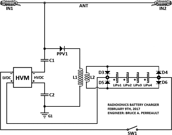
Look at the image for knowing the way I see it.

                      It will really appreciate to have your comment on it!

                      Next step, testing the theories.

                      You are shorting the antenna ions to ground in this diagram.

                      I see I have a few responses to give today. I will get to them by the end of today.

                      Comment


                      • Originally posted by fan1701 View Post
                        Battery pack shown in wrong polarity.

                        al

                        Thank you... I forgot to redraw them. Look at the drawing... it's fixed.
                        Last edited by radioionics; 02-10-2017, 04:51 PM.

                        Comment


                        • Originally posted by Wistiti View Post
                          Here is a picture of my first theorise (Connection of antenna to ground) sorry for the crappy picture.
                          I let it run for 15 min.

                          Im finally no sure it is it. cause the battery start at 12,35v and finish at 12,02v...

                          Nice build... you have done well. I suspect you don't have much further to get your batteries to charge, instead of drain. It appears that you have a nice white light. This is what we want to see. If the light was purple the circuit would be built incorrectly.
                          Last edited by radioionics; 02-10-2017, 05:43 PM. Reason: a letter was added where it was missing

                          Comment


                          • Originally posted by Wistiti View Post
                            Hehe! yes, you right!
                            Be sure it's not the first time it's happen either... I will learn!

                            Actually, you are learning quite well by "brainstorming." You are finding out for yourself what works and what doesn't work with the circuits that have been presented to this group.

                            Comment


                            • Originally posted by Wistiti View Post
                              Ok! I think we need some guidance. Bruce, can you give some help please?
                              It's the night here an I have to go sleep. My brain is boiling. Hope it will be a good night!
                              Ciao!

                              I might not be able to give guidance right away but I will when I get the chance.

                              Comment


                              • Originally posted by soundiceuk View Post
                                When Bruce says the grail is right in front of you he isn't kidding!

                                It's so similar to the original mirror circuit schematic you could leave everything in place.

                                If someone figures it out we are going to enter the paradigm shift.

                                It feels like the Scalar Waves (Radioionics) tutor left you an assignment / puzzle to figure out what scalar waves are, do and behave.

                                Bruce, someone called you "old".

                                Time to leave the class and retire? Haha

                                Well Paul, I not getting younger, for sure. I see that there are a few here who are very close and they don't even know it.
                                Last edited by radioionics; 02-11-2017, 12:09 AM.

                                Comment

                                Working...
                                X