 Tweet
Tweet
Originally posted by dragon
View Post
Moving forward with my obsession and a bunch of new tests... Originally my question to myself was why would there be a power draw on an open circuit, that is, the same draw that would be present in a closed loop. One would expect to see an "idle" draw on the transformer if it was an open circuit. The reduction in power when using the ant/grd then could be explained by the capacitive coupling. Calculating the reactive resistance showed that it was indeed running in a closed loop. The ant/grd having a 13kohm resistance gave a clear indication of what I saw as the drop in power consumption between this and the direct connection. With a 13k resistor in the closed loop circuit it performed like the ant/grd circuit. So what, if anything, is to be gained here?
I set out to build an artificial environment to replace the ant/grd yet still maintain the capacitive effect I was seeing. Thus the tube and wire - large surface area acting as a ground and small surface area as the antenna... the infamous "Ion Valve". Worked perfectly with slightly less input consumption. The capacitance measured in at around 55 pf giving me an over all resistance of around 75k. This corresponded closely to what I calculated. So then, what is the key mechanism that "brings in", "attracts", or otherwise supplies energy in excess of the original input?
In pondering this I also realized that with the added resistance ( ant/grd, ion valve ) there was an RC time constant involved here as well - a tiny delay in response, which may or may not have relevance..... The next several experiments ended in complete failure - the goal was to reduce capacitance even farther thus finding a maximum impedance that I could get by with that would still allow the system to run, hoping for a reduced input requirement yet still provide a reasonable output. Obviously I went to far and it simply became an open circuit once again...
I fashioned 2 plates that could be adjusted for distance, one large one small - quickie calculations on distance and size ( overall a "best guess"). At a gap of around 1.25 " there was noticeable activity in the gap, at just over 1" it flashed and maintained an arc. So, alright we had an output and all was running as expected, only a slight drop in input requirement which was disheartening, it dawned on me that the transformer couldn't do this on it's own. I'm using an 8kv transformer throttled by a 15uf cap so it's most likely running in the range of 4-5kv. The gap being an inch or more indicates a voltage far in excess of what the transformer alone would do.
Ending this portion of my investigation I observed; No energy in excess of input, nothing to indicate a reduction of input other than the inherent resistance, it functions solely as a closed circuit not as an open circuit... but an interesting development leading to a place to start a new investigation.
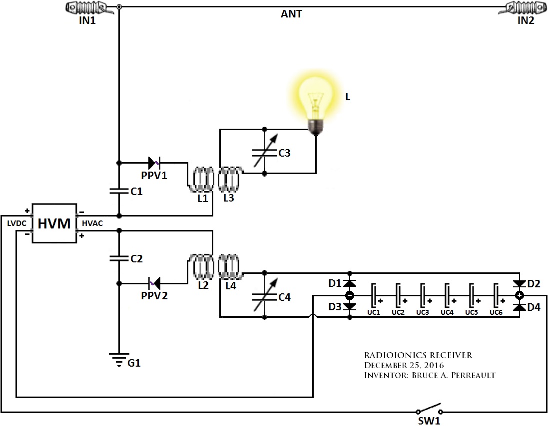
*A standalone ION VALVE is no more than a voltage regulator. It can be used to COUPLE with a source of ion potential energy.


Comment