Announcement

Collapse
No announcement yet.

Donald Smith Devices too good to be true

Collapse
X
 
  • Filter
  • Time
  • Show
Clear All
new posts

  • Originally posted by radioionics View Post
    Doh, the switich isn't closed.
    Hahaha! Your right!
    Here is my last works...
    just need to plug: hv source, antenna, ground and load!

    Attached Files

    Comment


    • Cheap PPV!
      Attached Files

      Comment


      • Guys; did you use air cap on your output??

        Comment


        • Originally posted by Wistiti View Post
          Guys; did you use air cap on your output??

          No cap on secondary at the moment.

          You made the same mistake i did in the beginning.. You mounted Hv-wire in wood.

          Comment


          • Originally posted by Mwtj View Post
            No cap on secondary at the moment.

            You made the same mistake i did in the beginning.. You mounted Hv-wire in wood.
            bad news! But thanks for the info....
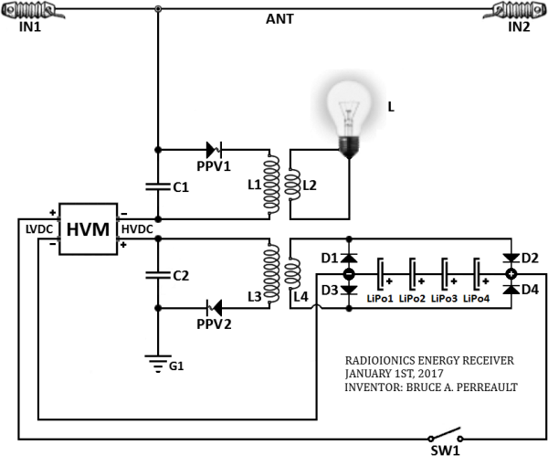
            I think I have to see it by myself before dismantling the PPV...

            Comment


            • https://youtu.be/3qA7SJODHdA

              Comment


              • a whole lot going on

                Paul
                Additional inspiration [see simple video

                https://ionpowergroup.com/how-it-works-on-earth/

                shared By member boonk at Stefan's forum
                Kapanadze Cousin - DALLY FREE ENERGY

                with gratitude and respect

                Chet K
                Last edited by RAMSET; 01-29-2017, 01:45 PM.
                If you want to Change the world
                BE that change !!

                Comment


                • v7.0.0 MIRROR BUILD


                  OK, enough for the pretense on the circuit. As you have come to realize, tuning isn't necessary. Why? Because the circuit is a radioionics (scalar wave) circuit. It isn't what most are used to seeing. Soon enough a few replicators will be ready to scale up the power capabilities of my unique "mirror circuit." When you are ready to take the next step you must be completely familiar with the low power proof of concept that has been presented so far. One slight mistake could take your life in an instant. If this happens you will be stone cold dead and nothing is going to return your life to you. Use extreme caution when you do reach the next stage. Respect the power!
                  Last edited by radioionics; 01-29-2017, 02:34 PM.

                  Comment


                  • Originally posted by radioionics View Post

                    OK, enough for the pretense on the circuit. As you have come to realize, tuning isn't necessary. Why? Because the circuit is a radioionics (scalar wave) circuit. It isn't what most are used to seeing. Soon enough a few replicators will be ready to scale up the power capabilities of my unique "mirror circuit." When you are ready to take the next step you must be completely familiar with the low power proof of concept that has been presented so far. One slight mistake could take your life in an instant. If this happens you will be stone cold dead and nothing is going to return your life to you. Use extreme caution when you do reach the next stage. Respect the power!
                    This is always the duality with any powerful tool. Power is dangerous: and yet power is useful. Bruce, thank you for sharing with us and helping us understand.

                    Comment


                    • Originally posted by radioionics View Post

                      OK, enough for the pretense on the circuit. As you have come to realize, tuning isn't necessary. Why? Because the circuit is a radioionics (scalar wave) circuit. It isn't what most are used to seeing. Soon enough a few replicators will be ready to scale up the power capabilities of my unique "mirror circuit." When you are ready to take the next step you must be completely familiar with the low power proof of concept that has been presented so far. One slight mistake could take your life in an instant. If this happens you will be stone cold dead and nothing is going to return your life to you. Use extreme caution when you do reach the next stage. Respect the power!
                      Thanks for sharing this valuable work, in my opinion tuning is related with the gathered particles , in the case of electromagnetic scalar radiation tuning is a part from the system , bigger charge carrier as example your system need more higher voltage for higher power , the risk of electricity can be minimized with the contribution of more experienced replicator .. when the path is clear minimal risk can be found .

                      Comment


                      • Originally posted by radioionics View Post

                        OK, enough for the pretense on the circuit. As you have come to realize, tuning isn't necessary. Why? Because the circuit is a radioionics (scalar wave) circuit. It isn't what most are used to seeing. Soon enough a few replicators will be ready to scale up the power capabilities of my unique "mirror circuit." When you are ready to take the next step you must be completely familiar with the low power proof of concept that has been presented so far. One slight mistake could take your life in an instant. If this happens you will be stone cold dead and nothing is going to return your life to you. Use extreme caution when you do reach the next stage. Respect the power!

                        Comment


                        • I did some more thinking on scaling up. The present secondary arrangement is completely inadequate to handle heavy currents at 500 KHz frequencies. Something like Litz wire would be optimal (although hard to find and expensive). Good old "super jumbo speaker wire" like Don mentioned a time or two might be a reasonable choice if the voltages in the secondary aren't too high. It's easy to obtain and relatively cheap. I have a small amount of 16 gauge on hand, it's what I've been using for low voltage interconnect wire. 16 gauge would be useful up to maybe 15 amps secondary current, although if my suspicions are correct it's going to get cold, not hot, when loaded down. This could bring its own set of challenges: insulation could get brittle at low temperatures and I expect condensation and even icing could be a problem. One thought I had was to encapsulate the whole unit in something like an aquarium (shades of Kapanadze?) and at least use desiccant, if not evacuate the whole thing. I doubt any normal aquarium could stand a reasonably good vacuum, though. I also have some much heavier duty high-speed diodes on hand, 30A current, 1000V and "ultrafast" speed. The tradeoff is that they have a much larger forward voltage drop than the Schottky diodes, at least 1.0V, probably 1.2V or more at full rated current. To achieve full rated current will require significant heatsinking.

                          Since I had the idea that eventually we would be reaching higher power levels, I have designed a shunt regulator arrangement capable of dissipating significant wattage to prevent the cap bank (or batteries) from overcharging. It consists of a 2N3055 transistor with the base driven by a 12V zener diode. If the voltage between the positive and negative rails of the DC output reaches 12.7V (the zener voltage plus the transistor base voltage), the transistor will begin to conduct and waste enough power to keep the voltage from rising further. With a proper heatsink on the 2N3055, it should be able to dissipate at least 50W of continuous power. With external resistors of 0.5 ohm or so it can handle higher power levels because then the transistor itself won't be taking all the heat. I already have some suitable power resistors on order.

                          Comment


                          • Originally posted by SERG V. View Post
                            For experimenters only !!


                            Check yourself !!
                            Hello,
                            I came across on the site
                            http://www.energeticforum.com/renewa...-true-344.html
                            the post # 10318. The is an interesting circuit, designated as "KOMANDOR". I would like to replicate it for the purpose for Science Experiments. If anybody has already replicated it or obtained the required information
                            Please tell me:
                            1. What type of wire is used.
                            2. How to wind the coils, turn to turn or move.
                            3. How are located the coils on the plastic pipe.
                            4.Should the capacitor adjusted in resonance or not.
                            5. For what the hot end of the Flyback is connected to the load.
                            6.Spherule on the secondary, as I understand it is a capacitor, how to choose it.
                            I would be grateful for any useful information .

                            Comment


                            • Originally posted by tswift View Post
                              I did some more thinking on scaling up. The present secondary arrangement is completely inadequate to handle heavy currents at 500 KHz frequencies. Something like Litz wire would be optimal (although hard to find and expensive). Good old "super jumbo speaker wire" like Don mentioned a time or two might be a reasonable choice if the voltages in the secondary aren't too high. It's easy to obtain and relatively cheap. I have a small amount of 16 gauge on hand, it's what I've been using for low voltage interconnect wire. 16 gauge would be useful up to maybe 15 amps secondary current, although if my suspicions are correct it's going to get cold, not hot, when loaded down. This could bring its own set of challenges: insulation could get brittle at low temperatures and I expect condensation and even icing could be a problem. One thought I had was to encapsulate the whole unit in something like an aquarium (shades of Kapanadze?) and at least use desiccant, if not evacuate the whole thing. I doubt any normal aquarium could stand a reasonably good vacuum, though. I also have some much heavier duty high-speed diodes on hand, 30A current, 1000V and "ultrafast" speed. The tradeoff is that they have a much larger forward voltage drop than the Schottky diodes, at least 1.0V, probably 1.2V or more at full rated current. To achieve full rated current will require significant heatsinking.

                              Since I had the idea that eventually we would be reaching higher power levels, I have designed a shunt regulator arrangement capable of dissipating significant wattage to prevent the cap bank (or batteries) from overcharging. It consists of a 2N3055 transistor with the base driven by a 12V zener diode. If the voltage between the positive and negative rails of the DC output reaches 12.7V (the zener voltage plus the transistor base voltage), the transistor will begin to conduct and waste enough power to keep the voltage from rising further. With a proper heatsink on the 2N3055, it should be able to dissipate at least 50W of continuous power. With external resistors of 0.5 ohm or so it can handle higher power levels because then the transistor itself won't be taking all the heat. I already have some suitable power resistors on order.

                              thick solar cable is an option? Almost the same as jumbo speaker wire.
                              Do you have a full schematic ? So i can make a nice pcb for it in eagle.
                              Last edited by Mwtj; 01-29-2017, 08:45 PM.

                              Comment


                              • Originally posted by Mwtj View Post
                                thick solar cable is an option? Almost the same as jumbo speaker wire.
                                Do you have a full schematic ? So i can make a nice pcb for it in eagle.
                                It's really simple, I pretty much described it. Even the base resistor is essentially optional. External pass resistors would go between the transistor collector and +V, and should be suitable resistance and power dissipation for the application. In this case, at 12V the desired dissipation might be 30A, so Ohm's law means we need 0.4 Ohms resistance and 360W power handling. Of course all the cables and connectors need to handle 30A as well, and the traces on the PCB need to be very beefy and probably solder reinforced.


                                Full discussion:
                                design - High power equvalient for a zener - Electrical Engineering Stack Exchange

                                For even more power dissipation these could be made in single 30A modules, like a brick. Just parallel multiple units to reach the desired dissipation. Designing a PCB for it would be great!

                                Comment

                                Working...
                                X