If this is your first visit, be sure to
check out the FAQ by clicking the
link above. You may have to register
before you can post: click the register link above to proceed. To start viewing messages,
select the forum that you want to visit from the selection below.
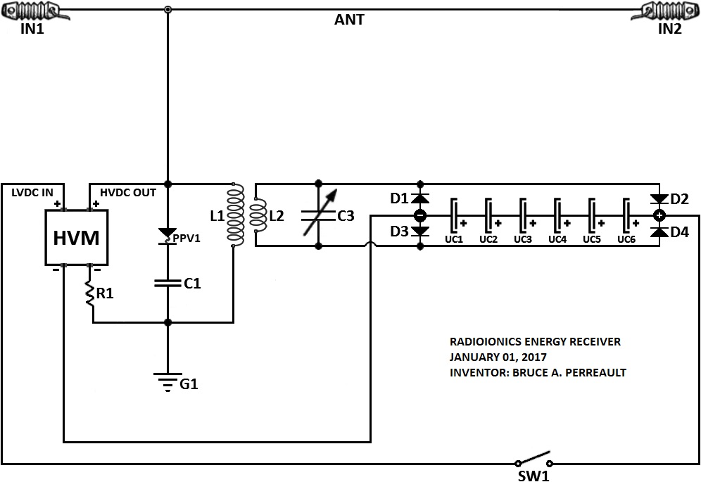
I looked at that too. I think it's supposed to be essentially one half of the mirrored circuit, and easier to build than the original circuit because you don't need a high-voltage variable cap. But the schematic looks like it has a problem, the L1 coil will just short the HV to ground. Thinking that there might be more than meets the eye, I took a few minutes and wired it up this way. Sure enough, all that happened was that the resistor got warm from the power dissipation. No spark, no oscillations. Perhaps Soundiceuk can fill us in....
Have you ever noticed while driving down a road in winter how the leave-less trees look so much like an electrical discharge? A huge trunk at the bottom to move large currents and thousands of tiny points reaching into the sky to dissipate tiny currents from each of the many branches.
Wouldn't it make more sense to mimic natures best example... ?
Just like a lightning-strike or human biology or the veins in a leaf.
Looking good, I like those stand-off insulators! I'm going to have to improve the insulation on my test rig considerably, at 26KV there are small leaks happening all over the place. I can only imagine how problematic it's going to be to get 100KV and higher....
Have you ever noticed while driving down a road in winter how the leave-less trees look so much like an electrical discharge? A huge trunk at the bottom to move large currents and thousands of tiny points reaching into the sky to dissipate tiny currents from each of the many branches.
Wouldn't it make more sense to mimic natures best example... ?
Yes, I thought of that too. For an antenna to get the best discharge characteristics into the surrounding air you would need a branching, dendritic, fractal structure terminating in sharp points. This would produce the most ion current for the smallest size antenna. But yes, it seems nature has already figured this out....
More progress on the test device, I wound the L3/L4 secondary. I took some test measurements with 5 turns and it seems that the voltage output from 2 turns will likely be enough so I wound it that way, 2/2 bifilar. I put an outer band around the turns to keep them in place, I didn't want to drill holes in the cardboard coil form and get the L3/L4 wires any closer to the L1/L2 wires. At higher voltages I think having the maximum possible separation is a good thing. I arranged most of the output side circuit, the diode bridge and the supercaps on the DC output side, and a light bulb on the AC output side.
More progress on the test device, I wound the L3/L4 secondary. I took some test measurements with 5 turns and it seems that the voltage output from 2 turns will likely be enough so I wound it that way, 2/2 bifilar. I put an outer band around the turns to keep them in place, I didn't want to drill holes in the cardboard coil form and get the L3/L4 wires any closer to the L1/L2 wires. At higher voltages I think having the maximum possible separation is a good thing. I arranged most of the output side circuit, the diode bridge and the supercaps on the DC output side, and a light bulb on the AC output side.
ps: my secondary to have only 2 turn to achieve the good inductance (10uh/ 11uh) for resonate with my air cap at 500khz.
Actually I haven't even measured the inductance of the secondary yet. I'm kind of with Dragon on this, I'm not sure why the cap is necessary. Due to the load on the secondary the Q will be really low and I don't think trying to resonate it will make much difference. But it's in the schematic, so I will try it both with and without when I test it. If the power gain effect shows up then it should be possible to extract a greater amount of power by increasing the secondary turns, it will mess up the normal relationship between voltage and amperage in the primary and secondary of the transformer.
Actually I haven't even measured the inductance of the secondary yet. I'm kind of with Dragon on this, I'm not sure why the cap is necessary. Due to the load on the secondary the Q will be really low and I don't think trying to resonate it will make much difference. But it's in the schematic, so I will try it both with and without when I test it. If the power gain effect shows up then it should be possible to extract a greater amount of power by increasing the secondary turns, it will mess up the normal relationship between voltage and amperage in the primary and secondary of the transformer.
Great progress Tswift.
Wistiti you need to hurry up
Put the multiplier in oil or parrafin wax. Limit the current on the multiplier. I have blown the diodes on my 6 stage multiplier @ 60kV because i did not know. Two times
Did the last test without cap on the secondary and with more turns. Used a 220v bulb.
 Tweet
Tweet


Comment