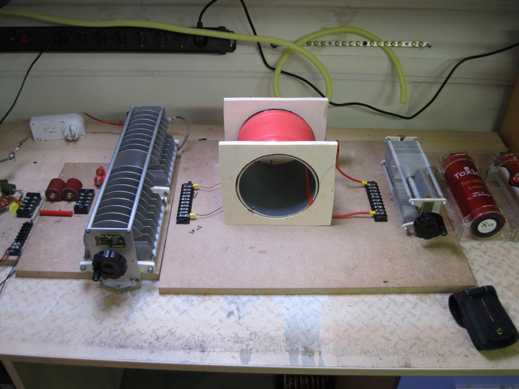
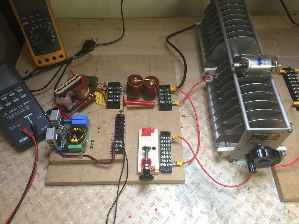
Announcement

Collapse
No announcement yet.

Donald Smith Devices too good to be true

Collapse
X
 
  • Filter
  • Time
  • Show
Clear All
new posts

  • Setup for testing.

    Copper wire is on its way. Yellow tube is going outside to the antenna. There are two ground connections behind the coil.
    Attached Files

    Comment


    • Originally posted by Gedfire View Post
      I see lasersaber is far more advanced than any other so called experts who have ever graced this forum.Yet this guy is ignored.

      Me thinks this just needs a scaled up version.

      https://www.youtube.com/watch?v=1RXolkA08uk
      What Lasersaber has done is great!

      However it has moving parts and is inferior.

      The only moving part in Bruce's design is the plasma spark that jumps the gap!

      It is also the only noise too. A quiet hiss.

      Comment


      • Gedfire I thought you was talking about Lasersabers atmo motor.

        Just watched the link...

        See what tswift and the others conjure up and then decide what is more advanced.

        Comment


        • Lasersaber of Joule Ringer Fame

          Originally posted by soundiceuk View Post
          Gedfire I thought you was talking about Lasersabers atmo motor.

          Just watched the link...

          See what tswift and the others conjure up and then decide what is more advanced.
          Well lets see eh?

          After studying most of Lasersaber's self running versions,I see many parallels to Don's devices and the ultimate secret.Self Resonance.That was how the original tesla devices ran.Rumkorf Coil at self resonance.Never saw the switching sections of teslas coils in Don's Books.That's the same principle in car horns and bells (electromechanical) Another thing is the core.Metglas and similar cores please,less turns needed..And finally, that bucking coil stuff...Volts on one side and amps on the other.

          Strangely enough I can't seem to find that very elusive metglas core of the right size:shoe box device size.I have two chinese no BS NST's.No GFI etc.But need a core.Metglas Core.
          Last edited by Gedfire; 11-22-2016, 11:02 PM.

          Comment


          • Originally posted by soundiceuk View Post
            What Lasersaber has done is great!

            However it has moving parts and is inferior.

            The only moving part in Bruce's design is the plasma spark that jumps the gap!

            It is also the only noise too. A quiet hiss.
            Bruce's machine? He could just use XRAYS.He knows this.Higher frequency striking metal.He had the patent in his Draft Document with his ion valve.He also knows the plasma will generate XRAYS UV and even gamma rays under certain circumstances.I know this because I have two Radiation detectors and plasma from my spark gap AND corona discharge cermaic ozonator produces copius amounts of XRAYs.

            Comment


            • Originally posted by Mwtj View Post
              Setup for testing.

              Copper wire is on its way. Yellow tube is going outside to the antenna. There are two ground connections behind the coil.
              You can use HV wire for a lead in from the antenna.

              What tube is it?

              Comment


              • Great! Get right on it.

                Tube is al little bigger than 6 inches ( 16cm).

                Unfortunaly i am only about a 300 feet above sea level. A little less than i thought
                Last edited by Mwtj; 11-24-2016, 08:26 PM.

                Comment


                • It will be interesting to see how much different elevations around the world differ with your replications.

                  Anyone live near the northern lights?
                  Last edited by soundiceuk; 11-24-2016, 09:29 PM.

                  Comment


                  • L2: 2" coils 25+50 turns of AWG 18
                    CAP L304: 115-550pF 250-500V
                    RES: AMPHENOL ???

                    Last edited by DigitalM; 11-25-2016, 06:09 PM.

                    Comment


                    • 1K Ohm AMPHENOL Multi-Turn Trimmer 992P

                      (CTM) 304 - 115 - 550 pF, 500v


                      Inductance uH:_67.0

                      Coil Length:___4

                      Coil Dia:______1-3/4

                      Turns per Inch:16

                      Wire Size:_____18

                      some data abouth smith coil

                      lc coil is 3/4
                      antena coil is 1/4
                      Attached Files

                      Comment


                      • Thanks a lot for HD fotos and your research.
                        However, I do not agree with coil devision. You can see 24(+-1) turns of antena coil.
                        So, we have 24+40 turns. Its 8 turns for 1/4 wave
                        L1 is part NO 3033 and 5 turns of L1 have same lenght as 8 turns of L2.

                        Last edited by DigitalM; 11-26-2016, 07:03 PM.

                        Comment


                        • Do, NO TRY.

                          Originally posted by soundiceuk View Post
                          Gedfire I thought you was talking about Lasersabers atmo motor.

                          Just watched the link...

                          See what tswift and the others conjure up and then decide what is more advanced.
                          I tell you this, the neon sign dimmer is in SERIES resonance to the rest of the circuit.Its all self resonance via the dimmer circuit.I tried the dimmer switch capacitor to car coil device.That's when i dawned on me that it was series resonance going on here.
                          Don had it on on most of his devices.

                          @Soundiceuk.The fun begins on page 23 of Bruce's Doc .See attached.If Don's Doc you mean, let me know.I have posted them before.

                          What I need now is a large metglas core....
                          Attached Files

                          Comment


                          • "Partial completed hv side

                            Waiting for stuff to complete the spark gap.

                            60kv capacitor total 1nf
                            10mOhm 25kv resistor
                            100pf 11kv aircapacitor
                            Glass vacuum capacitor 50pf 10kv if needed
                            Green cap 30kv 470pf
                            Two 20kv 100ma diodes.
                            Zvs driver with old style flyback 30khz
                            Black thick wire is going to antenna."


                            Great job! ZVS is very efficient!

                            Comment


                            • Well, it looks like everyone is making progress, very encouraging! Here is some of my latest activity. I have started adjusting the layout on the bench to resemble the final desired assembled result. I also took some measurements to find the output voltage from the secondary. It needs to more somewhat more than 12 volts but not hugely more than 12 volts. The voltage step-down ratio of the resonant transformer stage will be determined by the ratio of turns of course, but it's more complicated than this because (1) the flux coupling coefficient between the primary and secondary is not close to 1 and (2) the primary and secondary are quite different in size and have quite different inductance. There are formulas for all this of course, taken from standard electrical engineering and used commonly in Tesla coil design and ham radio practice:

                              V2 = V1*k*sqrt(L2/L1)

                              Where V1 is the input voltage to the primary, V2 is the output voltage from the secondary, k is the coefficient of coupling, and L1 and L2 are the respective coil inductances measured separately.

                              It's easy enough to put an LC meter on the coils to measure inductance, but how do you measure k? There are multiple ways, but one of the easiest is to measure the primary by itself, and then again with the secondary shorted. The measured inductance will be less and with a little algebra you can find k from these measurements. The formula is:

                              Lsc1 = (1-k^2)*L1

                              Where Lsc1 is the measured inductance of L1 with L2 short-circuited. So I did this and found:

                              L1 = 977 uH
                              Lsc1 = 857 uH

                              which gives k of about 0.35. It works equally well measuring the secondary while shorting the primary:

                              L2 = 29 uH
                              Lsc2 = 24.2 uH

                              and if you work the math it gives a fairly similar result, within experimental error. So as a whole this assembly should be expected to give a voltage ratio (going back to the first formula above) of about 0.06 ( k*sqrt(L2/L1) ), or a step-down ratio of around 16:1. If the breakdown voltage of the spark gap is set to something like 1500 volts, then the voltage at L2 should be something under 100 volts. This might be good enough, or I might have to reduce the turns on L2. At least to begin experimenting it's probably good enough.

                              A good resource on mutual inductance and coil coupling:
                              Coupling Between Coils
                              Attached Files

                              Comment


                              • All right, after calculating the step-down ratio, it's easy enough to put it to the test with the function generator. The function generator is driving the L1 coil at resonance (tuned for approximately 500 KHz), through a 10K resistor, with the oscilloscope measuring the voltage across both L1 and L2. The measured voltage across L1 was 15.0V peak-to-peak and the measured voltage across L2 was 0.816V p-p. This gives a measured step-down ratio of about 18, versus 16 by computation. Still definitely in the ballpark.

                                Note that for this test the cap across L2 is not used. It's strictly operating as an air-core transformer.
                                Attached Files

                                Comment

                                Working...
                                X