Announcement

Collapse
No announcement yet.

Donald Smith Devices too good to be true

Collapse
X
 
  • Filter
  • Time
  • Show
Clear All
new posts

  • ............


    you know it's possible for a separated plate to conduct the electricity the question now is how the capacitor charged ?

    how for a separated plates to carry electrical charge? there's a process let the capacitor to duplicate the electrical charges from one plate to another .. this process is caused by the induced electric field and not the magnetic field... Maxwell noticed the presence of magnetic field in the periphery of the capacitor under AC current and he gave us his famous displacement current equation to solve the problem of Ampere law since the circuit is open ...

    i have a new theory about displacement current the new concept to show it's the induced electric field which cause the capacitor to charge itself under AC mode... here you are the video :

    https://youtu.be/PyyTv2r1xlY


    physically the solution is pretty simple because the induced electric field find itself in a critical situation because it can't circulate inside a conducting plate, any conductor will produce a reversed electric field cancel the first main field that try to penetrate inside it but the situation in the rotating closed loop electric field is relatively complex...

    this field have to circulate in a closed loop but with the presence of conducting plates it will change this to form two closed loop instead of one, the two closed loop are connected together ... to understand this please see this small video about Quantum Entanglement & Spooky Action at a Distance :


    https://youtu.be/ZuvK-od647c


    the capacitor use the ability of electrons to spin up or down to charge each side with an opposite charge compared the other side and this what allow this simple device to carry electrical charges in AC current, each side can see the situation of other side and transmit this hidden information faster than light ... and this is the real complexity ...

    the shape of induced electrical field in a capacitor is complicated also, my theory about the new displacement current isn't complete... but i can see it as a good physical replacement of the old displacement current theory.

    there's other information can be given .....

    Comment


    • Originally posted by bugaian View Post
      Hello to all,

      thanks for hard work and good information posted in this thread.

      I was able to replicate Don's basic design using NST( 37Khz at 6kV) the only problem I have is that I am at a limit with spark gap. If gap is bigger a bit I get very useful output, but the problem is after a 15-30 minutes run the NST would shut down.

      Now running it at a limited spark gap power and getting about 200W, if I try to get more adjusting spark gap distance it just shuts down.

      Any ideas of how to fool the NST? I tried wih grounding and without grounding it my result are same.

      Anybody having same experiences?

      Thanks for sharing.
      Hey bugaian ...I am from the same country like you ..I understand,you live in Brasov ;I live in Zalau judetul Salaj...if you see this post please let me know how can I contact you ..I wish more details about your setup...You have used resonance to obtain useful output? How you have tuned your setup?

      When you have load at output the resonance didn,t go out of tune? How much input /output you have? ....I have an old electronics friend ..he tried don smith stuff without succes...but maybe he can help you with advices why your nst shutting down..maybe going warm and some protection inside shuting of automaticallyyour nst... did you tried to make homemade nst using FBT transformers and ZVS circuit? FBT can suport high voltages and have no protection to shut off..

      Regards Mihai

      Comment


      • Another suggestion to improve output would be to try moving the storage capacitor physically closer to the first tesla coil stage (the step-up stage). If it's close it will begin to affect coil tuning and if it's REALLY close it might arc either from the coil to the cap or internally within the cap case. I am also interested in other details about your setup and configuration if you would be able to provide them.

        Comment


        • Happy Birthday, Mr. Tesla!

          Comment


          • Originally posted by sinergicus View Post
            Hey bugaian ...I am from the same country like you ..I understand,you live in Brasov ;I live in Zalau judetul Salaj...if you see this post please let me know how can I contact you ..I wish more details about your setup...You have used resonance to obtain useful output? How you have tuned your setup?

            When you have load at output the resonance didn,t go out of tune? How much input /output you have? ....I have an old electronics friend ..he tried don smith stuff without succes...but maybe he can help you with advices why your nst shutting down..maybe going warm and some protection inside shuting of automaticallyyour nst... did you tried to make homemade nst using FBT transformers and ZVS circuit? FBT can suport high voltages and have no protection to shut off..

            Regards Mihai
            Salut/Hi MIhai,

            I did try several setups, and yes I did manage to implement a FBT and now I am experimenting with it leaving NST aside for now. What I managed to achieve with old setup was that battery bank from witch I feed inverter and NST would not go down and if I would set spark gap larger it would go up, but as I was telling already with a larger spark gap it would go off random times may in 30 min may be in 4 hours, something like that.

            About resonance, looks like with NST it was simpler since it gives a fixed nice 37KHz and with few caps you can adjust secondary coil to resonate, also as you add more capacitance to first coil you increase frequency on second coil, I was setting it a bit higher for example to 50Khz and when running it with load and grounding it would indeed go down to about 37-35 Khz. Also when grounding secondary coil you have a drop in resonance for me its not clear yet should these coils resonate with grounding or without on secondary coil. May be somebody else with more experience can tell?

            You can contact me in private bugaian [at] gmail

            Alex.

            Comment


            • Bugaian, if you have gotten this far then you ARE the person with experience around here. Only just a few people on this thread have ever claimed to see any power gain at all or looped the device, proving overunity. I personally have experimented with more variations of this device than I can count and although I feel like I understand it pretty well I have yet to have measurable success. Personally I would think the coil needs to be tuned for resonance with grounding connected, which as you say will drop the frequency. Can you provide any pictures of your setup?

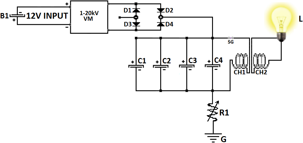
              As best as I understand it, the whole secret to the Don Smith style device and others like it, is as Zilano said long ago on this thread "hot to cold and cold to hot". When the storage capacitor receives a pulse of current, as Don said it "takes a snapshot" of the energy AROUND the capacitor. This is in no way "magnetic" as Don said, but SCALAR. It's not measurable at this point in the capacitor itself. It just looks like a charged capacitor with regular voltage and stored charge, but the stored charge has an extra flavor, a scalar characteristic with the imprint of the voltage around it when the charge was stored. Don discovered that this "cold" component of the charge is not subject to Lenz's law in the normal way. So when you put it through a transformer of any type you obtain overunity because the Lenz's law reaction is reduced. This is why the inverter or output transformer is necessary to see the gain in a Don Smith device.

              If you look at all of Don's various devices any prototypes, look at what they have in common. Think about the plasma ball device for instance. What does it do? The coil collects a pulse of current to feed the storage caps, and the caps are surrounded by a high voltage ambient environment at the point in time when this happens. The pickup coil on that device isn't even tuned for resonance. All that the well-known tabletop Don Smith setup is, is a bank of capacitors in the displacement field of a Tesla coil, with a provision to make sure they get a pulse of current when the voltage around them is high. After that you have to send the current from the storage capacitors through an output transformer of some kind to see overunity. I'm fairly sure that the paired/partnered secondary output coils are not necessary and that a single coil will do as well, but I haven't proved that for sure yet.

              Another trick seen on some of Don's devices is to use the battery to receive the ambient energy just as if it was another storage capacitor. This is done with the "kickback diode", which functions just like the diodes on the secondary coil feeding the cap bank. Then the battery just has to be close enough to the high voltage Tesla coil section to pick up enough power. This also makes the battery charge itself with cold electricity instead of hot, so that the NST stage will operate overunity, reducing the power draw from the battery, increasing the power available and multiplying the COP of the device.

              The main problem I'm having on my own bench is that none of my high voltage power supply options are powerful enough, about 15W max. This isn't enough power after the Tesla coil section to run an inverter on the output. With a more powerful flyback I think I could be having success.

              I wish you continued success in your experiments, and please keep the rest of us posted on your progress!

              Comment


              • Originally posted by tswift View Post
                Another trick seen on some of Don's devices is to use the battery to receive the ambient energy just as if it was another storage capacitor. This is done with the "kickback diode", which functions just like the diodes on the secondary coil feeding the cap bank. Then the battery just has to be close enough to the high voltage Tesla coil section to pick up enough power. This also makes the battery charge itself with cold electricity instead of hot, so that the NST stage will operate overunity, reducing the power draw from the battery, increasing the power available and multiplying the COP of the device.


                In Smith system the battery can be charged just by taking 4 times the length of the primary and connect the battery using this special length since he has standing waves generated around the system, this wire act just like an antenna, generating standing waves is a normal results of combing AC and DC in a resonating system by wrapping the AC around the DC component so you have useful radiant power ...

                Comment


                • Well, I partially agree with this. The standing waves are certainly true, it's how the whole device works, by "disturbing ambient". This can easily be seen just by moving an oscilloscope probe anywhere close to an oscillating coil in an LC circuit, especially a slayer exciter or real Tesla coil. But personally i'm not convinced that the wire length going to the battery has anything to do with it. The secondary rings with the primary because of the capacitor across it, not because the wire length is an exact multiple. Some experimenters have claimed that wire length or weight is important, but Tesla coil hobbyists have long ago disproved this, at least for normal Tesla coils.

                  My own opinion is that's solely a proximity effect by the battery picking up the standing evanescent wave in the near field around the oscillating coil. Because the battery is connected to ground but with a diode in the positive lead, on the positive half-cycle of the AC waveform (of the ambient voltage around the battery due to the ringing coil), then charging by induction will happen from ground and electrons will be pulled up to the battery's negative plate. Just as Zilano said, you can see this effect with a full avramenko plug connected from ground, with the diodes going to the battery terminals. Put the battery close to a ringing coil and it will charge just as a cap will. Unless your battery is very close to a very powerful Tesla coil the charging will be slow, fairly small current. This by itself is not overunity, I've tried it. What happens is that due to the ambient voltage outside (of the battery or cap) the charge transferred in this manner picks up an extra cold/radiant/scalar characteristic that then does interesting things once it goes through a transformer. Don did this on the back end, with the cap bank and the (not usually shown) output transformer. He also did this on the front end of the device with the battery and the NST, making it run overunity with very minimal current draw from the battery.

                  But of course in the absence of experimental proof, all this is just conjecture on my part. I am continuing to work on experiments on the bench to finally prove once and for all the exact mechanism of the overunity effects seen on these devices, and until that's complete then I could of course be wrong. Over my time investigating I have changed my opinions on things several times already and could certainly do so again given proof.

                  But the final thing that I think lays to rest the "1/4 wave" battery charging is Marc Belanger's video where he replicates a Don Smith style looped system with wireless battery charging via ambient from a NST.... but he does it at 60 Hz. How long is 1/4 wave for 60 Hertz? Very very long indeed, impractically long. Also, the wire length inside the NST in the video, whether primary or secondary, is completely unknown and not easy to determine. Yet Marc is able to reproduce the wireless battery charging and run it looped.

                  Comment


                  • Originally posted by med.3012 View Post
                    In Smith system the battery can be charged just by taking 4 times the length of the primary and connect the battery using this special length since he has standing waves generated around the system, this wire act just like an antenna, generating standing waves is a normal results of combing AC and DC in a resonating system by wrapping the AC around the DC component so you have useful radiant power ...
                    Hi,

                    looks like you are right on this one since I have 2 locations/rooms where I test. One is about 8 meters from battery bank and one is 1 meter from batteries. I do have different results from 2 locations and I could not explain it...will do more testing on that one.

                    Thanks.

                    Comment


                    • Originally posted by bugaian View Post
                      Hi,

                      looks like you are right on this one since I have 2 locations/rooms where I test. One is about 8 meters from battery bank and one is 1 meter from batteries. I do have different results from 2 locations and I could not explain it...will do more testing on that one.

                      Thanks.
                      Hi

                      welcome, nice to see your advance in the field, in reality i don't use the NST because it's very rare in my place, so i use the NE555 flyback oscillator, sometimes the simple transistor oscillator and finally for production it's the Mazzili driver for better performance but the frequency must be adjusted for resonance purpose .

                      recently i was thinking about some new design since we still have a common problem, it's the ability to attract ambient electrons especially the heavy electrons responsible for the production of electric current, in radio frequency the electrons take a similar form to a wave, this mean it appear to be smaller and swift,

                      i don't mean by heavy electrons they have more weight by they seem to have, i think this is related to the spin that produce magnetic field, each electron has a tiny magnetic field and the overall field will cease these electrons to move freely finally the gathered electric current will be small not because we don't have these electrons but because we don't have the proper condition to make them move faster !

                      Comment


                      • Very good. I believe it's all about correct treatment of electrons.

                        Comment


                        • Originally posted by boguslaw View Post
                          Very good. I believe it's all about correct treatment of electrons.
                          Yes it's all about the correct treatment of electrons, something similar to the lightning! according Don Smith it's over unity phenomena, the earth is the unity and above the earth ( cloud ) is over unity ! we need to condense the electrons in dynamic state so they will have both state, one dynamic and the other is static sometimes it's good to watch how the nature act !


                          Comment


                          • Metglas Terfonal D Nanoperm

                            Originally posted by soundiceuk View Post
                            Hi folks, lets bring a close to this.

                            Don's briefcase device was extremely efficient for lighting but was not self sustaining or even COP > 2.0


                            Don Smith 2016:


                            https://www.dropbox.com/s/7d3qwt4pzu...itors.mp4?dl=0


                            Just remembered a theory of mine.The middle tube of the device stated by Soundiceuk really should have a metglas,terfonal D ,ferrite,nano perm or mumetal inside.As there are very permeable to magnetic fields and works at higher frequencies.Just a thought.I mean, some of his other devices had cores present.So following the pattern we could conclude....

                            Comment


                            • This is an interesting publication from Vladimir Utkin, collected into Patrick Kelly ebook. It is related to overcoming the Lenz effect and make good reference to Don Smith designs:

                              Dealing with Lenz's Law

                              .
                              https://figueragenerator.wordpress.com/

                              Comment


                              • FYI - Electrostatic Induction

                                F.Y.I.

                                An interesting discovery (article) regarding "Electrostatic Induction" including experimental apparatus and mathematics (article in Russian). Work was conducted by Dmitry Dyudkin, Prof/Dr. of Technical Services; et. al., Donetsk National Technical University (Ukraine).

                                Article title: "SELF-ELECTRIC : electrodynamic induction"

                                Quoted from the first paragraph -
                                "For the current level of knowledge of physics occurrence of electric currents is an axiom of the impossibility of ensuring the Coulomb electric field (the field produced by electric charges, an electrostatic field) steady electrical current in a conductor."

                                Demonstrated, amongst other things, is the fact that electrostatic charges - when in motion - will generate "conventional (including current {i}) electricity." Link: (appears links are not allowed here - replace _ with h)

                                _ttp://electromaster.ru/modules/myarticles/article.php?storyid=42

                                [[ use "Im Translator" or other to convert to your native language]]

                                FIN
                                Last edited by Solarlab; 09-17-2016, 03:58 PM.

                                Comment

                                Working...
                                X