Announcement

Collapse
No announcement yet.

Donald Smith Devices too good to be true

Collapse
X
 
  • Filter
  • Time
  • Show
Clear All
new posts

  • Originally posted by janost View Post
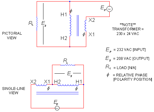
    The current in a transformer has phaseshift between the primary and the secondary of 180deg, 90deg in the first winding and 90deg in the second.

    If you connect them in series and revers one of the windings, the current will be in phase and will add.
    Hi janost. OK, I am having a bit of a hard time following what you mean. Do you mean something like this? Or are you talking about a dual secondary transformer where you wire the two secondaries in series in opposing fashion?

    Last edited by level; 02-26-2013, 08:28 PM.
    level

    Comment


    • Originally posted by level View Post
      Hi janost. OK, I am having a bit of a hard time following what you mean. Do you mean something like this?

      Yes.

      The current in the secondary is 90deg that of the primary if they are wound in the same direction.

      That is the pure nature of coils.
      It takes 90deg before the current catch on in the other winding.

      Comment


      • Originally posted by janost View Post
        Yes.
        The current in the secondary is 90deg that of the primary if they are wound in the same direction.
        That is the pure nature of coils.
        It takes 90deg before the current catch on in the other winding.
        Ok, I have never tried it. I updated the picture in my previous post. It is the buck boost transformer setup which I think citfta was referring to as well. Reminds of the way some people have guessed the kapanadze coil might be wired up. I will give it a try and see how it works...
        level

        Comment


        • New idea

          Ok Level, understood, i assume after seeing lot of diagrams, that the configuration for C,L and spark is the following one:


          Right? I consider that being spark gap between C and L it discharges the V on Cap when V rises enough short-circuiting L and creating a big current through it.

          If someone would be able to explain what's the difference of:

          - LC in parallel with sparkgap in series
          - LC in series with sparkgap in series
          - LC in parallel with sparkgap between both in series
          - LC in parallel with sparkgap between both in parallel

          it will be a great information contribution, since Don don't explain it so well, and i think many of you have tested it yet.

          Comment


          • Originally posted by ritualsiniestro View Post
            Right? I consider that being spark gap between C and L it discharges the V on Cap when V rises enough short-circuiting L and creating a big current through it.
            Yes, that is how it works in that configuration. That is a common sparkgap arrangement used in tesla coils. Don did have the sparkgap in the arrangement you showed on your previous schematic on his demonstration board for this circuit, but when I tried it that way it worked very poorly. However, my pulse capacitor C1 and L1 were not selected for resonance with L2 in my test setup, but if you select C1 and L1 for exact resonance with L2, the way you had the sparkgap in your previous diagram might work. I am not sure how well it will work though. I haven't tried it with C1 and L1 tuned for exact resonance for the secondary, but I intend to test it when I can get a chance. If I test it I will report back here on how well it works.

            Maybe Clarence here has tried that arrangement when C1 and L1 are tuned for exact resonance? Clarence, have you tried ritualsiniestro's previous sparkgap (GDT) arrangement, and does it transfer energy well through to the secondary if C1 and L1 are tuned for exact resonance to match L2?
            Last edited by level; 02-26-2013, 10:50 PM.
            level

            Comment


            • Originally posted by level View Post
              Yes, that is how it works in that configuration. That is a common sparkgap arrangement used in tesla coils. Don did have the sparkgap in the arrangement you showed on your previous schematic on his demonstration board for this circuit, but when I tried it that way it worked very poorly. However, my pulse capacitor C1 and L1 were not selected for resonance with L2 in my test setup, but if you select C1 and L1 for exact resonance with L2, the way you had the sparkgap in your previous diagram might work. I am not sure how well it will work though. I haven't tried it with C1 and L1 tuned for exact resonance for the secondary, but I intend to test it when I can get a chance. If I test it I will report back here on how well it works.

              Maybe Clarence here has tried that arrangement when C1 and L1 are tuned for exact resonance? Clarence, have you tried ritualsiniestro's previous sparkgap (GDT) arrangement, and does it transfer energy well through to the secondary if C1 and L1 are tuned for exact resonance to match L2?
              Hello Level,

              clarence,

              In answer , in my previous build I found that tuneing the Cap value according to the inductance value of L1 to match the tuneing cap value and inductance value of L2 so that both have the EXACT same resonate frequency value with respect to each other, will give you L1 transmitter to L2 receiver transfer you desire. you do need to stay as close to the chosen frequency value that you have chosen for the very best results. Also I believe the capacitors should be parallel next to the coil and not have the sparkgap interferring with its reasonant coil operation. the spark gap is to give the spike pumping effect and not a reasonance effect. (my thoughts!)

              Don never did show any capacitors or resistors or diodes on his models ( except for the board model he displayed at 1996 convention) for a good reason and it was not selfish at all. think about this, the board model was straight tesla design! it was a moveable TUNER design! the caps only brought the system L1 close to reasonant frequency and then the moveable L1 did the fine tuneing! I dont believe he wanted to open himself up to mamoth criticism from the public by showing defined cap values on his models and then people say that his units didnt work, because he new ahead of time that NO TWO EXACT SAME BUILDS WOULD react exactly alike!!! caused by different wire sizes (even tho same guage!) which make for different inductances, etc. I am sure all of you can comprehend that if you built two exact same builds that their inheirent values wouldnt be the same.

              back to subject, please be aware that ALL major components of any system you build should all be tuned to the SAME reasonant frequency! Driver, L1, L2, and then filter the frequency you have used down to a 50 or 60 Hz value to feed your load transformer. I really believe you will see good results.

              additionaly I will give you my view on the frequency range to use. from many observations when persueing tutorial programs I have become aware that capacitors and inductors when subjected into and possibly sometimes below the mega hertz range begin to act oppositely to each other ( cap begins to behave as an inductor and an inductor begins to behave as a capacitor). for that reason I began to take note of the frequency ranges don used on his builds. as far as I can tell his frequecy ranges were mostly between 30khz and say up to 50 khz. Its just my thoughts but if he had his results in that range thats where Ill operate. at present Im set to operate at 35.1 khz because thats where I set the length of my L2 (28ft) which made my L1 (7ft).
              made everything neat and easy.

              one more observation and Im thru, when you are checking the reasonate operation of your L1 coil if you are at Exact Full reasonance the L1 impedance should have limited the current draw down to about 1 ma and therefore have given you max voltage across your coil. that is what the L1 coil operation is all about - minimum current with max voltage. Also know that excessive current across L1 will make a GDT run HOT! and probably burn it up quickly and rob you of voltage across L1.

              hope this helps members, because that is my only intent.
              as always, mike, onward!
              Last edited by clarence; 02-27-2013, 04:24 AM. Reason: forgot part of the answer!

              Comment


              • Anyone knows more details about jammer kits? The audio jammer, Gps jammer, jammer 433 mhz, and common cell phone jammer . happy to share more sources with you.

                Comment


                • Originally posted by clarence View Post
                  ...
                  Also I believe the capacitors should be parallel next to the coil and not have the sparkgap interferring with its reasonant coil operation. the spark gap is to give the spike pumping effect and not a reasonance effect. (my thoughts!)
                  ...
                  Hi Clarence. Thanks for the info and tips. I was more wondering if you had done tests and if so, if you had achieved good energy transfer to the secondary using that sort of sparkgap arrangement. It is common to use the sparkgap either in parallel to the NST (or whatever high voltage source you are using), and have the pulse cap in series with the primary L1 winding, between the sparkgap and L1, or to have the exact reverse and have the capacitor in parallel to the NST and have the sparkgap in series with the primary winding, between the pulse cap and L1, for driving tesla coils, and this does not interfere with the resonance tuning effect on the primary. Those two sparkgap arrangements are tried and tested methods and do achieve good resonant energy transfer from the primary to the secondary on a tesla coil.

                  However, Don Smith did have the GDT wired in differently on his demo board with the dual secondary coils. It is possible he did it that way purposely to achieve a different type of desired effect, or possibly he wired it that way on the demo board to try to throw people off a bit. I was thinking that it may be the latter, but I did not try Don Smith's GDT arrangement with exact matching resonance tuning between primary and secondary.

                  The reason I was inclined to think he might have been just trying to throw people off by altering his wiring a bit on his demo board, is because in the Don Smith 'Bonus' videos Don Smith clearly stated that tuning for resonance between the primary and secondary wasn't necessary to get results, other than you just need to have the secondary be an even multiple length of the primary length, and that he had just demonstrated it that way previously because people expected that sort of configuration. There seems to be a major contradiction there. However, the way Don Smith described the simplified circuit arrangement in the Bonus videos does not appear to be workable based on my own testing. I made a setup of exactly the way Don Smith described the circuit in the Bonus videos, with a 12VDC NST directly driving the primary of the tesla coil arrangement, and it just would not work that way. NST has nowhere near enough current drive for that sort of arrangement. I don't know what the explanation is for what Don Smith said in the Bonus videos, but I will try Don's demo board GDT arrangement with the primary tuned for exact matching resonance for the secondary, and if it does not work I think I will move on to other avenues of experimentation.
                  Last edited by level; 02-27-2013, 11:30 AM.
                  level

                  Comment


                  • Hi, what do you think about this shematic i found on:

                    SMIT / FreeEnergyLT / FreeEnergyLT

                    It seems to me a good schematic, the problem to achieve a 220V 50Hz output seems to be resolved here, but as always we have to replicate and test it for a empirical verification. I'm sure im gonna test it as soon as i would able.

                    I thought to do a simplification on this circuit replacing the 555 inverter by a low power pure sine computers UPS.

                    Here the schematic:


                    And here the block diagram a bit modified, but keeping the arrangement of the previous diagram:


                    What do you think about this arrangement? No capacitors are used here.. I don't know if this would work until i test it, but without capacitor it seems that the L1 and L2 coil may be any length you want to use while L1 = 1/4 of L2, agree?
                    I think the big point here is the step down coil, including a modulation coil seems very interesting.
                    Maybe the input voltage have to be adjusted until we get 230V at output of this step down arrangement?
                    Again it seems to good to be true, but since this schematic appeared on the net, it means that someone tried and tested it.
                    I will try it for sure, i will posts any results i get.

                    Have a good day

                    Comment


                    • Originally posted by ritualsiniestro View Post
                      What do you think about this arrangement? No capacitors are used here.. I don't know if this would work until i test it, but without capacitor it seems that the L1 and L2 coil may be any length you want to use while L1 = 1/4 of L2, agree?
                      I think the big point here is the step down coil, including a modulation coil seems very interesting.
                      Maybe the input voltage have to be adjusted until we get 230V at output of this step down arrangement?
                      Again it seems to good to be true, but since this schematic appeared on the net, it means that someone tried and tested it.
                      I will try it for sure, i will posts any results i get.
                      Have a good day
                      That circuit looks like maybe a circuit arangement that someone came up with to try to replicate the Kapanadze device. It may be worth a try. There are a few odd things in that circuit diagram, so you may have to play around with the circuit a bit. I have no idea if that is supposed to be a working circuit or just someone's general idea of something to try. The fact that they show a 2N3055 bipolar transistor as a FET in the inverter circuit diagram does not appear to be a good sign however. Zilano was someone who posted to this thread in the past, and although I don't know if they came up with that particular circuit diagram variation, I think some people tried Zilano's suggestions and did not get any working results.
                      Last edited by level; 02-27-2013, 05:13 PM.
                      level

                      Comment


                      • Originally posted by ritualsiniestro View Post
                        Hi, what do you think about this shematic i found on:

                        SMIT / FreeEnergyLT / FreeEnergyLT

                        It seems to me a good schematic, the problem to achieve a 220V 50Hz output seems to be resolved here, but as always we have to replicate and test it for a empirical verification. I'm sure im gonna test it as soon as i would able.

                        I thought to do a simplification on this circuit replacing the 555 inverter by a low power pure sine computers UPS.

                        Here the schematic:


                        And here the block diagram a bit modified, but keeping the arrangement of the previous diagram:


                        What do you think about this arrangement? No capacitors are used here.. I don't know if this would work until i test it, but without capacitor it seems that the L1 and L2 coil may be any length you want to use while L1 = 1/4 of L2, agree?
                        I think the big point here is the step down coil, including a modulation coil seems very interesting.
                        Maybe the input voltage have to be adjusted until we get 230V at output of this step down arrangement?
                        Again it seems to good to be true, but since this schematic appeared on the net, it means that someone tried and tested it.
                        I will try it for sure, i will posts any results i get.

                        Have a good day
                        Hello ritualsiniestro,

                        Clarence,

                        the original Don circuit you show with the modulation coil to achieve the output 50hz came from Patrick J Kelly site chapter #3. it gives the full info on the arrangement and I believe the arrangement is shown as comeing from Zilano Zane Zeis.

                        Again I would like to point out that the length of the L2 coil is first determined to match the frequency of the system you are going use. In Don circuit shown that frequency for the whole build was determined by the output of the driver he chose, namely 35.1khz! he did not show any caps for resonance as was his usual omittance practice. if a builder does not use a cap value in agreement with the inductance value of the coil (in this case L1) then the driver will just brute force its frequency on the coil which is not the best scenario! (like using a shotgun to hit a flying skeet-maybe hit it maybe not with respect to resonance of coil).
                        When making a build always determine the length of L2 FIRST! WHATEVER KHZ frequency your driver will have then simply divide 988 by that frequency and that will give you the wire length for your L2 coil!!!! do not be concerned about dividing 988 by MHZ value!! the KHZ value is a HARMONIC of the MHZ value so just cut to the chase and divide by your driver KHZ frequency and you will obtain the correct length, excluding lead lengths (but that's another subject entirely). the length of L1 will simply be 1/4th of the L2 length.

                        I think that if a builder is CRITICALY EXACT in his L2 wire length that when L1 is resonating properly and thereby transmitting that it will talk to L2 without any problem and L2 possibly would not need a resonate cap parallel with it.

                        the homemade isolation transformer that the modulation coil is to surround looks like a project in itself.

                        Im not sure that the 555 IC circuit you show was include by Patrick in his Chapter three PDF but maybe it was included in an update, I will have to check.
                        LOL as always, mike onward!

                        Comment


                        • Ritualsiniestro, this is the way that Don Smith had his Gas Discharge Tube (sparkgap) wired in on his dual output coil demonstration board. See attached. I intend to give this a try with the primary tuned for exact resonance to match the secondary resonant frequency to see how it compares to the other standard ways which I mentioned above that tesla coils are commonly driven. I will report my results back here.

                          Clarence, this is the Don Smith GDT arrangement I was referring to. Just want to be sure I understand you correctly. Have you tested with this particular GDT arrangement, and if so, did it give you good results?
                          Last edited by level; 04-05-2016, 11:09 PM.
                          level

                          Comment


                          • Originally posted by stupify12 View Post
                            The tesla coil should be like this. Try to short circuit the not resonance coil to any output, just to prove if the shorting can interfer with the resonating coil.
                            Hey stupify12

                            Very Impressive. I see youve read Teasls, Writings And Researcghes book. People say all the time Tesla never had any free energy devices. They just look at your circuit or others like it and assume the power supply is just not shown. But if they had really read the book they would understand the ***POWER**** is coming from the Ether,Zero point, Ambient what ever. And Tesla put it out in plain site on how to get all the energy you need. I am currently on the last few chapters,but if you can get past some of the borring parts there is alot of Free Energy Info there. Its just hidden in plain site. Anyway, congrats on paying attention.

                            Best Regards on your quest
                            SLOW-N-EASY

                            P.S. The answer on how Tesla powered his electric car is in the XXIX chapter. He just stepped up the voltage from the ether with the transisters of that era from the electronics store with 2 large rods as antennas.

                            Comment


                            • Originally posted by level View Post
                              Ritualsiniestro, this is the way that Don Smith had his Gas Discharge Tube (sparkgap) wired in on his dual output coil demonstration board. See attached. I intend to give this a try with the primary tuned for exact resonance to match the secondary resonant frequency to see how it compares to the other standard ways which I mentioned above that tesla coils are commonly driven. I will report my results back here.

                              Clarence, this is the Don Smith GDT arrangement I was referring to. Just want to be sure I understand you correctly. Have you tested with this particular GDT arrangement, and if so, did it give you good results?
                              Hello level,

                              I had just started a reply to say no I hadn't used the GDT that way when I remembered the post of my old build recently. go to page#292 and my post #8735 and pull up the thumbnail and you will see the pink glow of the GDT between two smoothing caps and it is in series!

                              that build was not entirely successful as I stated but the success was not hampered in any means by the operation of the GDT. I believe at that time their was a total of 8ma across it. even tho the success was limited as far as output through L2 was concerned you can see that there was voltage through L2 by the orange neon bulb attached to L2 terminal strip. my problem then was my driver and cap values for L1. hope this helps. LOL

                              as always,mike,onward!

                              Comment


                              • Ok, I tried a quick test setup for the Don Smith sparkgap/GDT arrangement I posted above. It gave some very poor results. My air core transformer arrangement was setup to be resonant at around 106 kHz on both the primary and secondary using parallel caps, but I was driving the primary tank circuit with a 60 Hz NST, so that is probably why I got the very poor results that I got. Basically the sparkgap only fires very weakly and completely silent, with a bright violet and very steady glow, and my sparkgap also became very hot, whereas it remains completely cool when using the common sparkgap arrangements where the sparkgap is located in the tank circuit. I think the reason the sparkgap became so hot in this arrangement is because there was only very low energy being transferred to the air core transformer's secondary, so most of the power was getting dissipated in the sparkgap.

                                I have attached a couple of scope shots showing the sparkgap firing pattern I was getting using the 60Hz NST, and the air core transformer secondary voltage waveform. Voltage values shown in the scope shot are not actual voltages, as I was just holding the scope probe near the sparkgap and secondary coil to see the waveform shapes and frequency.

                                My next test will be to use a 12VDC NST, and have primary and secondary tank circuits on the air core transformer tuned to the exact same frequency as the NST, as Clarence suggested. I think that should give much better results. Have to wait till I get a new 12VDC NST for this second test though, as my other one blew on me.
                                Last edited by level; 04-05-2016, 11:09 PM.
                                level

                                Comment

                                Working...
                                X