Announcement

Collapse
No announcement yet.

Donald Smith Devices too good to be true

Collapse
X
 
  • Filter
  • Time
  • Show
Clear All
new posts

  • i still believe there is benefit to using the coils, but i just think that there was a reason Don's briefcase had no inductors (according to him)
    and the odd other devices using only capacitors (commercial mod and plasma tubes )

    i plan to improve on my setup, and possibly go back to using coils if and when i find an increase using them (Kapanadze-style improvement)

    im planning on the input set for 48 watts as i did for lighting the two 50 watt bulbs... but only power 1 bulb, and run the excess power to the source.

    ...but i have to clean up the output, or run it directly to a cap and battery?
    that's a problem as my invertor shuts down when NST goes on
    but i'll figure a way
    In the beginner's mind, there are many possibilities.
    In the expert's mind there are few.
    -Shunryu Suzuki

    Comment


    • Originally posted by Farmhand View Post
      The idea is kind of like this, the plates would be all 1/4 circle segments, one
      plate fixed and connected to the HV, two other plates opposite each other and
      insulated form each other and connected to the primary windings of the
      transformer by slip rings or such other way so that they can be spun in close
      proximity to the fixed and charged capacitor plate, as the rotating plates passed
      the capacitance sould increase to maximum then decline to nil when the next
      one begins it's pass. There could be variations, maybe there could be two fixed
      plates one positive and one negative. But the theory would be that energy
      would be transferred to the rotating plates as they passed the fixed charged
      plate and this could be stepped down and transformed to AC by the transformer. The plate spacing would depend on voltage.
      This maybe not scaleable to 60 Hz. Just an idea. And by design very
      dangerous, almost a rotary guillotine.

      I would actually like to try this in small scale at high speed, but a certain
      amount of engineering is involved and commitment.

      This is my old drawing, it's a bit rough.


      Level, I'm flattered, I think I have a "feel" for it but I'm not very technical, I
      struggle with the numbers. I'ts nice to be able to connect up the big coil and
      show people who haven't seen such things before.

      Oh the coals and ash around the ground stake I used just because I thought
      it might improve things.

      Cheers
      Are you meaning something like this?

      Comment


      • Originally posted by mr.clean View Post
        im planning on the input set for 48 watts as i did for lighting the two 50 watt bulbs... but only power 1 bulb, and run the excess power to the source.

        ...but i have to clean up the output, or run it directly to a cap and battery?
        that's a problem as my invertor shuts down when NST goes on
        but i'll figure a way
        hi buddy, my NST running with pure sine wave inverter.

        not a self runner, but maybe in the future
        Don Smith Table Top Device Part 3 - YouTube

        Comment


        • Originally posted by mr.clean View Post
          i plan to improve on my setup, and possibly go back to using coils if and when i find an increase using them (Kapanadze-style improvement)

          im planning on the input set for 48 watts as i did for lighting the two 50 watt bulbs... but only power 1 bulb, and run the excess power to the source.

          ...but i have to clean up the output, or run it directly to a cap and battery?
          that's a problem as my invertor shuts down when NST goes on
          but i'll figure a way
          I don't know that much about batteries, but the voltage being applied to the halogen bulb is probably fairly high voltage spikes that may be in the KV range at the voltage spike peaks. If you were to apply those HV spikes to a lead acid battery or gel cell, it might well damage the battery or maybe even cause the battery to explode, but I don't know enough about batteries to say for sure. It would be good if you can step down the voltage first. One way is to use a step down air core transformer tuned to resonate with the HV pulses, and then convert to DC, but you say that using your NST and sparkgap messes up your inverter and you would be back to using coils again as well. 
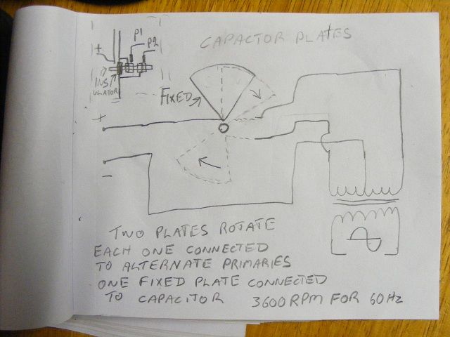
Off hand I can't think of an easy solution, but somebody else may have some other ideas. Something that really makes me wonder about Don Smith's devices is that the ones he showed all seemed to be incomplete in the sense of missing pieces that would make the extra power that is supposed to be generated usable. I mean 3000VDC to 7000VDC is not a useable form of voltage output. That's why I would be inclined to step the voltage down as AC to a suitable voltage first and then convert to DC, but that doesn't seem to be the way Don Smith did it on his dual coil device. He apparently converted to high voltage DC, and that was the output on that demo board. It doesn't seem to make sense...
          level

          Comment


          • Originally posted by ctbenergy View Post
            hi buddy, my NST running with pure sine wave inverter.

            not a self runner, but maybe in the future
            Don Smith Table Top Device Part 3 - YouTube
            cool man, keep going
            In the beginner's mind, there are many possibilities.
            In the expert's mind there are few.
            -Shunryu Suzuki

            Comment


            • Originally posted by algavrik View Post
              Hello Zilano!
              I'm in process of building Don Smith board device.
              Could you please clarify quick question for me. I read all the forum through and studied ur older deleted posts but could not find the information.

              Looking at Don Smith board device the secondary coil with 17+17 turns has CW winding direction.

              What winding direction does have primary L1 coil with 5 turns? CW or CCW?

              Thank you!

              A.
              hi Al
              Dynatron has posted his build and he winds all CW i believe, it's a matter a phase.
              if you wind cw primary, and then ccw secondary, they are phased 180, if cw secondary, then In phase with primary.
              Of course there is a slight lag, but anyway. i have found that it doesnt matter, it does matter with the secondaries tho,
              i phase the secondaries together to parallel them +-+-, whereas Don and Dynatron have them +--+.
              That works great if your diodes can effectively deal with the volts, current, and switching speed
              On my large double helix board from vid 30A, i have added now 3 parallel diodes each rated 30kv20mA... and they still are failing HOT... (that's 1800 watts!)
              and still overheating and flaming out!

              So i have given the smaller scale a try, but personally having better luck with secondaries separately tuned and parallel connected...

              ...that all being said, forget the coils, and read back a few pages
              Best performance yet, with no coils... and ~resonance~ is still involved

              Although i may use step down trafo
              Last edited by mr.clean; 01-18-2013, 11:21 PM.
              In the beginner's mind, there are many possibilities.
              In the expert's mind there are few.
              -Shunryu Suzuki

              Comment


              • i dont meant to toot my own horn, but in case anyone missed these.
                I present Don's "commercial model" concept design...
                part1
                42A Don Smith Device: Simplifying - YouTube
                part2
                42B Don Smith Device: further understanding - YouTube
                In the beginner's mind, there are many possibilities.
                In the expert's mind there are few.
                -Shunryu Suzuki

                Comment


                • question

                  hey i just noticed something very cool

                  i ran the recent system for about 10 minutes, running 2 of the DC 50 watt bulbs, and have a 10 watt 1 ohm resistor in-line with the supply, and one also in-line with the load...

                  ...the load resistor is RED HOT and the supply resistor is slightly warm.

                  shouldnt both resistors be the same??.....

                  http://img651.imageshack.us/img651/5757/imagenxpa.jpg
                  Last edited by mr.clean; 01-19-2013, 12:57 AM.
                  In the beginner's mind, there are many possibilities.
                  In the expert's mind there are few.
                  -Shunryu Suzuki

                  Comment


                  • Hi
                    You can do what you want if you don’t understand how the atom works, you will never get it right you have to nock off electrons from the atom to get free energy
                    Maybe if you study that we could get better results
                    Best to all

                    Comment


                    • Originally posted by African View Post
                      Hi
                      You can do what you want if you don’t understand how the atom works, you will never get it right you have to nock off electrons from the atom to get free energy
                      Maybe if you study that we could get better results
                      Best to all
                      Hi African. When using a high voltage to create corona discharge, this is basically accelerated ionization or electron avalanche. Ionization occurs when electrons are stripped from atoms. When electrons recombine with ions, energy is released. A sparkgap discharge causes a lot of ionization.
                      Mechanism of Corona Discharge
                      level

                      Comment


                      • @Mr.clean Thank you for posting a schematic of your circuit .
                        William Reed

                        Comment


                        • on that subjecj

                          There is materials that you can bombard with high voltage sparks and they would react by creating more electrons and every one will knock more of it,it becomes a knock on efeect it is called the Townsend discharge, look and you will find Dont shoot the messanger

                          best regards

                          Comment


                          • this is a must-see...
                            Eric Dollard 2007 Presentation - Misconceptions of Electricity and More - YouTube

                            JJ Thompson and Steinmetz came to the same conclusion that the conductor does not conduct, it translates the electrostatic and magnetic.
                            And Maxwell figured out that electricity flows in the insulators, not the conductor.
                            i may have the odd thing wrong, i dont claim to know exactly what the human eye cannot see, but those are some of the experts.

                            i dont mean to sound rude, but it sounded like unconstructive criticism... if im doing something wrong "and not understand the atom"... then what is the correct method?
                            hehe offer a solution, rather than a problem
                            In the beginner's mind, there are many possibilities.
                            In the expert's mind there are few.
                            -Shunryu Suzuki

                            Comment


                            • MR Clean

                              I have tried some projects but no luck at this time, i did however followed yours and i am very impressed with what you have achieved so please forgive me if i gave you the wrong idea it was not in anyway to take away from what you have done it is only to ad another perspective to some possible things
                              Best Johan

                              Comment


                              • Originally posted by rosehillworks View Post
                                @Mr.clean Thank you for posting a schematic of your circuit .
                                no problem im pretty happy with it
                                In the beginner's mind, there are many possibilities.
                                In the expert's mind there are few.
                                -Shunryu Suzuki

                                Comment

                                Working...
                                X