If this is your first visit, be sure to
check out the FAQ by clicking the
link above. You may have to register
before you can post: click the register link above to proceed. To start viewing messages,
select the forum that you want to visit from the selection below.
Today I was playing with the circuit of the toroid with two caps in series to the SG and I managed to light a 240v bulb 25w ok it was dim but by more windings maybe I will acquire that power.
Thanks.
It takes maybe a minute or 2 to load .. but then you can zoom and drag and klick on some links. You can also view it Full Screen.
The Schematics section is on the top, or above ( english? ) .
I don`t know where to start yet maybe some one has a tip .. what schematic.
I am currently inspired to follow Blue Serge schematic ..totaly on the right side of the Donzelina 2012 doc.
Utopia Now
Last edited by Utopia Now; 10-25-2012, 03:52 PM.
Reason: forgot to say teh sch. were from Zilano.
Here is something for you Kapanadze/Don Smith guys:
This circuit uses a car ignitioncoil wired backwards.
It runs the HV winding in series resonance from a 6V AC wallwart at 50Hz resonance (the line frequency in Europe).
At resonance, even though the voltage feed to the circuit is only 6V, the voltage drop over the capacitor and coil is about 5-6KV so the CFL-tube lights up.
The reason for the CFL is that without it the capacitor blows up.
What is even more interesting is that there is 5KV over the HV-winding and stepped down by about 85:1, there is low voltage AC output on the primary winding with a stepped up current.
For 60Hz line freq the capacitor needs to be changed.
I also found stokers posts very interesting. He points out that the weight of the L1 coil has to be 4 times the weight of L2 coils. So the cross sectional area of L1 should be 16 times that of L2, not 4 times, when it is 1/4 the length of one of the L2 coils. Of course assuming they are both the very exact same material. Anyone tried this?
Another thing he says the wire length from HV supply to L1 coil has to be 1/4 of the frequency. Here i have problems to follow him. He means 1/4 of the wavelength of the resonant frequency? And how to exactly measure this with the diodes, spark gap and caps in this line?
Im playing since 2 months with my smith replication and so far im not having overunity i think. With around 10-12 watt input to my Flyback transformer i can make a 25 watt buld flash very very bright, but only every 1-2 seconds for perhaps 1/10 second. I have connected the bulb via a 470 volt surge arrester in parallel to my charge cap bank.
Will keep on trying and report when i get kilowatts
Hello Mainsen,
Can you post or show a schematic .. with earth ground etc and also tell how your earth ground is made ... I buried a copper plate in my garden and a possible second earth grounding i will connect to the water pipes coming into my home. And do you use fast diodes.
Greetings Utopia Now
When I build Tesla coils, the three rules are followed:
1) Primary coil maas = secondary coil mass
2) Primary coil length = 1/4 secondary coil length
3) Primary coil frequency = 1/4 secondary coil natural resonant frequency.
you want a circuit that finds its own resonance, with this circuit the limiting factors will be the core and wire resistance, that and the coil connections are wrong Simple DIY Induction Heater - RMCybernetics
you must pull the magnetic field apart from the center out in both directions, its asymmetrical.
study the dual rail
Here is something for you Kapanadze/Don Smith guys:
This circuit uses a car ignitioncoil wired backwards.
It runs the HV winding in series resonance from a 6V AC wallwart at 50Hz resonance (the line frequency in Europe).
At resonance, even though the voltage feed to the circuit is only 6V, the voltage drop over the capacitor and coil is about 5-6KV so the CFL-tube lights up.
The reason for the CFL is that without it the capacitor blows up.
What is even more interesting is that there is 5KV over the HV-winding and stepped down by about 85:1, there is low voltage AC output on the primary winding with a stepped up current.
For 60Hz line freq the capacitor needs to be changed.
Now go figure
Interesting Stuff,
I am curious though.
Have you tried this?
What if i put 50 khz same voltage instead of 60 hz?
We saw Don lecture at a Tesla Conference in Salt Lake where we also were lecturing. He was a nice man, but every aspect of his lecture and demonstrations were pure deception. Some of it was clever, and others nonsense.
One nonsense demo was to take a modern "Violet Ray" Tesla Coil and charge a plate capacitor. He claimed the device drew energy from the earth and this explained the ability to draw sparks from the plate opposite the one he was charging with the machine. It was unreal.
Another similar demo, yet clever, was was a bipolar Tesla Coil with the secondary coils tapped at their midpoint. He claimed again the coil generated free energy and to prove it he shorted the two ends of the coils together and proceeded to draw sparks from the mid point. After all, if the coils were shorted all the energy was consumed... however on close inspection, the clever man wound the coils so that the opposite ends gave the same sign current - so that shorting the outer turns only put the two secondaries in parallel (both at the midpoint and the ends).
Most of the lecture had photos only and no real demos of anything. A lot of bizarre claims, like small magnet wire coils having the ability to transmit 100s of amps...
For the sake of conversation, everything was little more than props.
When I build Tesla coils, the three rules are followed:
1) Primary coil maas = secondary coil mass
2) Primary coil length = 1/4 secondary coil length
3) Primary coil frequency = 1/4 secondary coil natural resonant frequency.
Hopefully that helps.
Cheers!
Hi T1000, Don't you mean to say the input frequency is 1/4 the resonant
frequency of the secondary ? The primary coil should be tuned to resonate at
the same frequency as the secondary coil. The input discharge frequency can
be a fraction of the resonating frequency, I find 1/3 to the best fraction.
The quote below also explains why a system needs to tuned with the
intended load in place.
Strictly speaking the primary frequency should match the secondary frequency, but when a streamer forms on the toroid it adds capacitance to the circuit and causes the resonant frequency to drop, something that is often overlooked by a lot of people. The amount that it drops will vary depending on how long the streamer is, and where, or indeed if, the streamer strikes anything.
The way you have written it implies the primary resonant frequency should be
1/4 the resonant frequency of the secondary, like you are saying that if the
secondary is 1/4 WL resonant at 100 kHz the primary should be 1/4 WL
resonant at 25 kHz.
I think the primary should be resonant at the same frequency as the
secondary. The input frequency to the primary can be lower.
jeff_behary, I agree with you, the capacitor plate demo is a joke and simply
shows displacement current as in a capacitor. Don Smith was a fraud in my
opinion.
When I build Tesla coils, the three rules are followed:
1) Primary coil maas = secondary coil mass
2) Primary coil length = 1/4 secondary coil length
3) Primary coil frequency = 1/4 secondary coil natural resonant frequency.
Hopefully that helps.
Cheers!
Thank you T1000 that feels good .
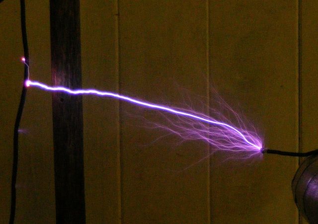
Here my still playing around with whale wave forms.
I did it with a gas discharge tube and I had to play with the voltage input power till these forms repeated fast ..about 80000 times a second.
Here some Links for other people to keep up the good faith in Tesla Don Kapanadze technologies
 Tweet
Tweet


Comment