Announcement

Collapse
No announcement yet.

Donald Smith Devices too good to be true

Collapse
X
 
  • Filter
  • Time
  • Show
Clear All
new posts

  • Originally posted by ewizard View Post
    Thanks janost! That helps me a lot. One other question since I'm not too familiar with how ratings work on GDT's. I'm looking at some now from a suppler that have a 500 volt breakover voltage and a 10 amp peak current. Would that be a good choice or do I need lower/higher ratings?
    As far as I can see the GDT only fires the SCR at a certain voltage on the AV plug capacitor.
    What about stacking NE2's with current limiting resistor then you can increase or decrease firing voltage.
    Or what about a big line of Zeners to fire the SCR.
    Just A thought as I don't have any GDT's on hand
    Comment


    • Originally posted by ewizard View Post
      Thanks janost! That helps me a lot. One other question since I'm not too familiar with how ratings work on GDT's. I'm looking at some now from a suppler that have a 500 volt breakover voltage and a 10 amp peak current. Would that be a good choice or do I need lower/higher ratings?
      500v is to much unless your stepdown transformer have a primary made for that voltage.

      I use an FL-tube starter as GDT and it fires around 200v.

      Comment


      • Strung circuit configuration

        Originally posted by janost View Post
        My SCR is a BTY-79 screwtype that can handle 10amps.
        It doesnt need to be that heavy so anything that can handle 350v 2A will work.

        The relay I use is a 6v and it will work with 12v relays but remember that the ignitioncoil generates 20000v on a 12v supply and the diodes have to be able to take the high voltage.

        Not sure the 1N4007 can handle 20Kv and you may need several diodes in series.

        I plan to use solid state switching but it was easy to test it with a relay.
        A mosfet controlled by an Arduino so that the currentdraw can be controlled in a feedbackloop.
        Janost,
        Thanks a bunch. You might want to have a look at this SFG circuit by Daniel Jackson to drive much bigger loads from your charge pump.

        http://www.overunity.com/143/www-ove...ch/attach/620/

        or

        SFG Revised_Dec_12_05

        "Once the circuit is fully charged, the electron deposit accumulated up at terminal
        a. charges the negative plate of C7 which in turn pushes electrons off of C7's positive
        plate and out through series blocking diode Dd. C7 acts as an electron deposit reservoir and as a buffer capacitor for momentary instantaneous current peaks."


        I plan to use solid state switching but it was easy to test it with a relay.
        A mosfet controlled by an Arduino so that the currentdraw can be controlled in a feedbackloop.


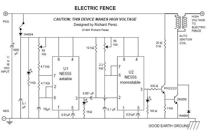
        Electric Fence – 20KV pulses by Richard Perez


        Regards,
        HS

        Comment


        • Originally posted by promt View Post
          To get your SG working in this setup you need somewhere 0.7-1.0a input;
          and output you have 70v 5a, means you have around 60% OU;
          pls check your meters, it's probably 5ma.
          Would you show pictures of your setup.
          Thank you.
          Excuse me

          Have you tried charging a 330uF electrolytic to 200VDC and shorting it with a screwdriver?
          The bang can weld your screwdriver to the terminals.

          If I connect a 230v 60w bulb to the loaded cap it will flash.

          The SCR needs 1.5v 30mA on its gate to fire and when it does it turns on its path between the anode and the catode at a rate of 100V/uS.
          That means that in 2uS the full potential in the cap is connected to the primary winding and even if the GDT goes out the SCR wont disconnect until all the current is gone.

          That is around 10A in just a couple of microseconds and that makes the transformer ring even if its secondary is shorted and a 400VA trans has a huge E-I core, about 3Kg so when it rings down it will deliver even more than 5Amps on its output if loaded.

          The thing here is to charge the 330uF up again as fast as possible.

          What do you mean by 0.7-1.0A?

          Comment


          • To attach tandem variable pots for freq adjustment

            Originally posted by harishsingh View Post
            hello HS,
            do you have any idea of how to insert tandem hi and lo variable pots to have a frequency variable output with this circuit? thanks for your consideration, mike onward!

            Comment


            • Originally posted by harishsingh View Post
              Janost,
              Thanks a bunch. You might want to have a look at this SFG circuit by Daniel Jackson to drive much bigger loads from your charge pump.

              http://www.overunity.com/143/www-ove...ch/attach/620/


              Regards,
              HS
              I really like this and Im trying to get a grip on it.
              Even after the 3rd reading trough it is still a massive thing to understand.

              But as I said, its good.

              Comment


              • Originally posted by harishsingh View Post
                Janost,
                Thanks a bunch. You might want to have a look at this SFG circuit by Daniel Jackson to drive much bigger loads from your charge pump.

                http://www.overunity.com/143/www-ove...ch/attach/620/

                or

                SFG Revised_Dec_12_05

                "Once the circuit is fully charged, the electron deposit accumulated up at terminal
                a. charges the negative plate of C7 which in turn pushes electrons off of C7's positive
                plate and out through series blocking diode Dd. C7 acts as an electron deposit reservoir and as a buffer capacitor for momentary instantaneous current peaks."


                Electric Fence – 20KV pulses by Richard Perez


                Regards,
                HS
                So after reading that, Smiths devices relied more on the balance of caps and diodes then the actual precision of the coils they powered? Could smiths power source circuitry be daisy chained like in the Pdf and eliminate the need for the coils all together?

                Comment


                • Originally posted by nicknewbie View Post
                  So after reading that, Smiths devices relied more on the balance of caps and diodes then the actual precision of the coils they powered? Could smiths power source circuitry be daisy chained like in the Pdf and eliminate the need for the coils all together?
                  Yes, I belive so.

                  But even after 5 readings I dont get how the output becomes negative in respect to ground (point A and point B in the examples)

                  I just dont get it.
                  May have to try a build.

                  2 supercaps and 5 diodes with a load.
                  Measure the input current and the load current and it will show if it can be scaled up.

                  I definitely belive that there is something with capacitors being the counterpart to coils.

                  If you short a 12v battery with a screwdriver you can hardly see the sparks.
                  Do the same with a cap charged to 12v and there is a loud pop.
                  Last edited by janost; 07-30-2012, 05:29 PM.

                  Comment


                  • This is the new SEP (Super Electron Pump)
                    400VA stepdown and a hipower ignitioncoil, 36Kv.

                    Last edited by janost; 05-03-2013, 11:55 PM.

                    Comment


                    • joule to uf conversion

                      Hi all!
                      can someone guide me how to convert a 473 joule 2000 volt capacitor into a known uf or Farad unit.
                      Thanks

                      Comment


                      • Originally posted by janost View Post
                        This is my super electronpump using an ignitioncoil and relayticker with a timing cap.

                        I know the relay will probably break after a couple of hours.
                        It is very easy to build using simple parts around a 6v SPDT relay, an ignitioncoil and a 400VA stepdown transformer.

                        The output is 400watts and will charge a Lead-Acid battery and will selfrun with a currentdraw of only 20mA.

                        [ATTACH]11848[/ATTACH]
                        Hey JANOST

                        I am very impressed with your Simple Circuit. Could it be upscaled to increase voltage and amps.

                        I am going to build one myself and experiment with it. What is the part # for the thyrister?

                        Could another Auto Coil be put at the end of the circuit to increse output? I guess I will have to try it.

                        Would be interested in the specs on the thyrister though.

                        Impressive , Good Luck

                        Comment


                        • Originally posted by janost View Post
                          This is my super electronpump using an ignitioncoil and relayticker with a timing cap.

                          I know the relay will probably break after a couple of hours.
                          It is very easy to build using simple parts around a 6v SPDT relay, an ignitioncoil and a 400VA stepdown transformer.

                          The output is 400watts and will charge a Lead-Acid battery and will selfrun with a currentdraw of only 20mA.

                          [ATTACH]11848[/ATTACH]
                          I am curious ; you use a 400VA stepdown transformer and therefor you think the output will be 400 watts (400=400) ! Or did you really measure 400 Watts real power output ?

                          Comment


                          • Originally posted by janost View Post
                            This is my super electronpump using an ignitioncoil and relayticker with a timing cap.

                            I know the relay will probably break after a couple of hours.
                            It is very easy to build using simple parts around a 6v SPDT relay, an ignitioncoil and a 400VA stepdown transformer.

                            The output is 400watts and will charge a Lead-Acid battery and will selfrun with a currentdraw of only 20mA.

                            [ATTACH]11848[/ATTACH]
                            Can you post a video of your setup and input, output, ect.?

                            Comment


                            • Originally posted by SLOW-N-EASY View Post
                              Hey JANOST

                              I am very impressed with your Simple Circuit. Could it be upscaled to increase voltage and amps.

                              I am going to build one myself and experiment with it. What is the part # for the thyrister?

                              Could another Auto Coil be put at the end of the circuit to increse output? I guess I will have to try it.

                              Would be interested in the specs on the thyrister though.

                              Impressive , Good Luck
                              You can use any thyristor that can take 350v 2A and it should work.

                              You dont need 2 autocoils.
                              The thing is to charge the capacitor in the AV-plug fast but 2 coils?

                              Go with one.

                              Comment


                              • Originally posted by EMCSQ View Post
                                I am curious ; you use a 400VA stepdown transformer and therefor you think the output will be 400 watts (400=400) ! Or did you really measure 400 Watts real power output ?
                                The thing is to make the transformer ring.
                                When it does you have put a huge mass swinging and that is energy.

                                Comment

                                Working...
                                X