Announcement

Collapse
No announcement yet.

Donald Smith Devices too good to be true

Collapse
X
 
  • Filter
  • Time
  • Show
Clear All
new posts

  • insulation

    @nutgone

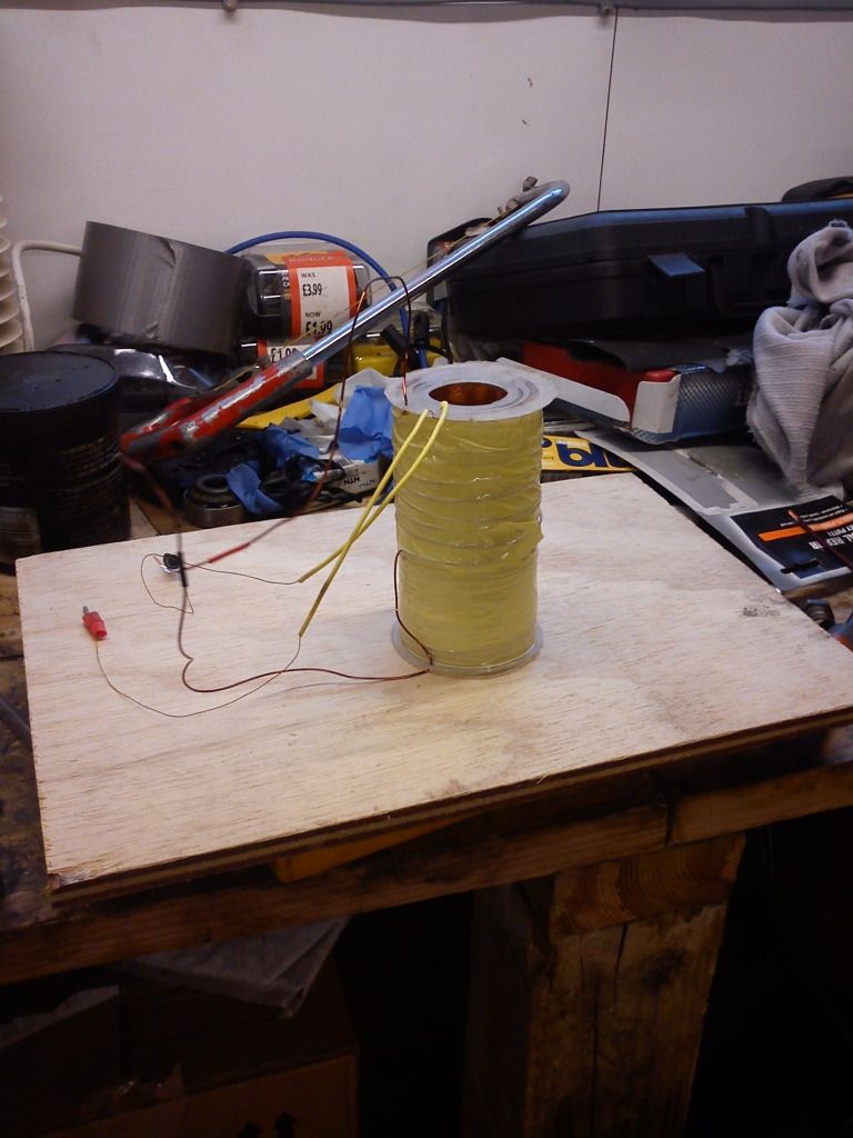
    dont know what voltage your step up coil produces, but 1 layer insulation tape between the hv coil and low voltage primary seems to me not enough if they are so close to each other

    Comment


    • Originally posted by nutgone View Post
      Hi Jacqui & thanks for that.
      That's the first thing that crossed my mind when it happened, & I think it could be part of the reason, as the bodies of the VRs are only in contact with the wooden board, but it doesn't quite explain the other problems I was having with the spark gap only working when I bought the earth wire into close proximity with the VRs.

      I do intend to use acrylic, or some other board which is a better insulator (or just better insulated terminal blocks).


      Do you have a schematic of your circuit?


      Thanks again Zilano. The coil was freshly wound yesterday & tests fine with a tester.

      Could it be that the 8 turn primary is wrapped around the outside of the 4000 turn secondary???
      I've also got 5 ferrite rods in the middle, maybe they're helping, maybe they're not???

      Anyway, I will have another little play today, at some point. I've got other stuff to get on with as well (life goes on).

      BTW, I used proper winding tape over my coils (the light yellow stuff you see in the pics), there is a layer of this in between the primary & secondary windings as well, so they should be insulated against each other.
      I bought the tape specially, as I didn't want to use PVC insulation tape. Also this is higher temperature than normal tape, but I stayed away from the fibreglass tape, as I'm told that can have a bad effect on certain transformers.

      This device is just a toy right now, as there are no capacitors involved in the HV side, & nothing is tuned to resonance. I was reading around 6v from my output coil at one point, but the most I connected to it was a multimeter.
      the 8 turn coil can be wound on outside but use a tube to wind on so u can slide it for adjusting on top of ur secondary coil. am still amazed why u got shocked i cant find any reason why it happened.

      rgds
      zelina

      Comment


      • Zilano I have two Microwave capacitors about 1.5uf each with bleeder removed.
        Can I get something from these atleast now? What is Don's battery charger in this circuit?
        Thanks
        Attached Files

        Comment


        • Originally posted by SLOW-N-EASY View Post

          Sense I used minni coils for my transformers.Which are just as powerful as pvc tubing coils. Best of Luck

          Regards
          S-N-E

          Good to hear of your success.

          So you have two mini bobbins, one for L1-L2, and one for L3-L4?
          Both bobbins are wound the same? 9" #26 MW wound on top of 36" #30 MW?
          I am assuming #26 MW means 26 AWG magnet wire?
          Is the L4 coil open ended as in your schematic?
          Air core, or welding rods?
          Do you have any clear pics of your bobbins?
          Any video of your setup running?

          Thanks for sharing
          Last edited by RAD-HHO; 05-27-2012, 03:05 PM. Reason: One more question
          Rick

          Comment


          • @nutgone
            Make sure you run entire setup fron battery source in first place. So no loops with mains power.
            The second thing is, if you still get shocked from variable resistors, this is what all exciters do. So on that point you can put HV cap between earth and your circuit then try to charge it up and unload over spark gap into load.. Have fun!

            Comment


            • data for home made caps

              When capacitors are connected in series, the total capacitance is less than any one of the series capacitors' individual capacitances. If two or more capacitors are connected in series, the overall effect is that of a single (equivalent) capacitor having the sum total of the plate spacings of the individual capacitors. As we've just seen, an increase in plate spacing, with all other factors unchanged, results in decreased capacitance.

              Thus, the total capacitance is less than any one of the individual capacitors' capacitances. The formula for calculating the series total capacitance is the same form as for calculating parallel resistances:

              When capacitors are connected in parallel, the total capacitance is the sum of the individual capacitors' capacitances. If two or more capacitors are connected in parallel, the overall effect is that of a single equivalent capacitor having the sum total of the plate areas of the individual capacitors. As we've just seen, an increase in plate area, with all other factors unchanged, results in increased capacitance.

              Thus, the total capacitance is more than any one of the individual capacitors' capacitances. The formula for calculating the parallel total capacitance is the same form as for calculating series resistances:

              As you will no doubt notice, this is exactly opposite of the phenomenon exhibited by resistors. With resistors, series connections result in additive values while parallel connections result in diminished values. With capacitors, its the reverse: parallel connections result in additive values while series connections result in diminished values.

              Capacitances diminish in series.

              Capacitances adds in parallel.

              above data is for non polarized caps.

              In theory, capacitors can be coupled both in series and parallel. If you need a 100MF cap and have two at 50MF, you can connect them in parallel, and that will give you 100MF (and same voltage rating as each). If you couple them in series, you get half the capacitance, and double voltage rating. But coupling electrolytic capacitors in series to get higher voltage rating must generally be discouraged. For this to work, you must be sure that the two (or more) caps share the voltage load properly; a resistor network can augment this, but if leakage currents are markedly different or the capacitors age differently, you are looking at a potential disaster, so do this only as a last resort, if at all.
              Last edited by zilano; 05-27-2012, 03:56 PM.

              Comment


              • I just grabbed a 473 page document that hartiberlin (OU admin) found on the TPU and also some excellent Don Smith material in this I haven't seen before. The author of the document has really put a lot of work into analyzing a lot of information in great detail. I think anyone interested in replicating Don Smith's work work will benefit by looking at this and in particular pages 449 to around 453 as he states this IS the secret to successful Don Smith replication. He backs up his work with a lot of math, diagrams, tables and graphics. I've downloaded it from scribd.com but as scribd requires an account and some uploading to get files I have re-uploaded it to rapidshare so everyone can grab it easily. Click Here to download from rapidshare.com (PDF file)
                Last edited by ewizard; 05-27-2012, 05:27 PM.
                There is no important work, there are only a series of moments to demonstrate your mastery and impeccability. Quote from Almine

                Comment


                • Ewizard Book Query

                  Hi Ewizard,

                  What's the title of that book? Thanks.

                  Best Regards,
                  David Fine


                  Originally posted by ewizard View Post
                  I just grabbed a 473 page document that hartiberlin (OU admin) found on the TPU and also some excellent Don Smith material in this I haven't seen before. The author of the document has really put a lot of work into analyzing a lot of information in great detail. I think anyone interested in replicating Don Smith's work work will benefit by looking at this and in particular pages 449 to around 453 as he states this IS the secret to successful Don Smith replication. He backs up his work with a lot of math, diagrams, tables and graphics. I've downloaded it from scribd.com but as scribd requires and account and some uploading to get files I have re-uploaded it to rapidshare so everyone can grab it easily. Still uploading for a few more minutes - will post a link shortly. You don't want to miss this document!!!

                  Comment


                  • The original title as I got it was 88066842-Marko-Rodin-coil-Steven-Mark-TPU-Tom-Bearden-MEG-Sweet-VTA-SQM-Annis-Eberly-generator-6th-Edition.pdf but I dropped the numbers (88066842-). Despite that title there is a whole section on Don Smith as his work does relate to some of these others. I have just taken a quick look so far at this document but I'm extremely impressed with it's detail and info. I will add that the author apparently does not have English as his primary language but you would hardly know that as he does extremely good with English - just a bit of an odd take on some things and himself - rather comical at times. While he claims he's just an ordinary Joe who's done this work I tend to think he's more along the lines of a genius (which he claims he's not).
                    Last edited by ewizard; 05-27-2012, 05:38 PM.
                    There is no important work, there are only a series of moments to demonstrate your mastery and impeccability. Quote from Almine

                    Comment


                    • Originally posted by ewizard View Post
                      I just grabbed a 473 page document that hartiberlin (OU admin) found on the TPU and also some excellent Don Smith material in this I haven't seen before. The author of the document has really put a lot of work into analyzing a lot of information in great detail. I think anyone interested in replicating Don Smith's work work will benefit by looking at this and in particular pages 449 to around 453 as he states this IS the secret to successful Don Smith replication. He backs up his work with a lot of math, diagrams, tables and graphics. I've downloaded it from scribd.com but as scribd requires an account and some uploading to get files I have re-uploaded it to rapidshare so everyone can grab it easily. Click Here to download from rapidshare.com (PDF file)
                      A massive from me for that!

                      Great find

                      Comment


                      • Thank You!!

                        Thanks Ewizard!!

                        Originally posted by ewizard View Post
                        The original title as I got it was 88066842-Marko-Rodin-coil-Steven-Mark-TPU-Tom-Bearden-MEG-Sweet-VTA-SQM-Annis-Eberly-generator-6th-Edition.pdf but I dropped the numbers (88066842-). Despite that title there is a whole section on Don Smith as his work does relate to some of these others. I have just taken a quick look so far at this document but I'm extremely impressed with it's detail and info. I will add that the author apparently does not have English as his primary language but you would hardly know that as he does extremely good with English - just a bit of an odd take on some things and himself - rather comical at times. While he claims he's just an ordinary Joe who's done this work I tend to think he's more along the lines of a genius (which he claims he's not).

                        Comment


                        • LCR metter

                          I understand , for experimenting with don smith device is need an good lcr meter.....

                          A profesional one cost thousand of dollars that I cannot afford...
                          So, I have possibility to buy this model of lcr metter http://www.extech.com/instruments/re...LCR200data.pdf

                          Zilano,if you see my post please give me an advice...what you think..is worth to spend my money on this lcr model ?


                          Thanks

                          Comment


                          • Don's circuit

                            I meant what can I get from this setup? Can I light up a heater?
                            Attached Files

                            Comment


                            • Originally posted by sinergicus View Post
                              I understand , for experimenting with don smith device is need an good lcr meter.....

                              A profesional one cost thousand of dollars that I cannot afford...
                              So, I have possibility to buy this model of lcr metter http://www.extech.com/instruments/re...LCR200data.pdf

                              Zilano,if you see my post please give me an advice...what you think..is worth to spend my money on this lcr model ?


                              Thanks

                              wellthe meter u posted as pdf is good. it covers the range u need.

                              (well find an lcr meter which can measure from pf range to uf range and from uH to mH also there is a cheap way to make ur own LCR meter as under)


                              Very Accurate LC Meter based on PIC16F628A

                              Accurate LC Meter Part's List:

                              1x 16x2 LCD Display with Green / Blue Backlight
                              1x PIC16F628A Programmed Microcontroller
                              1x LM311 IC
                              1x Accurate LC Meter PCB with red solder mask
                              1x Enclosure
                              1x Gold Plated Machined 18 DIP IC Socket
                              1x Gold Plated Machined 8 DIP IC Socket
                              1x L/C Pushbutton Switch with Black Cap
                              1x Tactile momentary reset switch with Black Cap
                              1x Gold Plated 16-PIN LCD Female Header
                              1x Gold Plated 16-PIN LCD Male Header
                              1x Gold Plated 2-PIN Header
                              2x Gold Plated 1-PIN Header
                              1x 4.000 MHz Crystal
                              1x High Precision 82uH Inductor
                              1x 5V Ceramic Reed Relay
                              1x LM7805 Regulator
                              1x 10K LCD Contrast Trimmer
                              2x 1000pF High Precision WIMA Capacitor
                              1x 100nF High Quality WIMA Capacitor
                              2x 10pF High Stability Capacitor
                              2x 10uF Panasonic Capacitor
                              1x 10 1% Metal Film Resistor
                              1x 1K 1% Metal Film Resistor
                              2x 6.8K 1% Metal Film Resistor
                              1x 47K 1% Metal Film Resistor
                              3x 100K 1% Metal Film Resistor

                              Accurate LC Meter's Technical Specifications:

                              Voltage Supply: 6 - 16V
                              Accuracy: 1%
                              Full Automatic Ranging
                              Inductance Resolution: 10nH
                              Capacitance Resolution: 0.1pF

                              LC Meter's Inductance Measurement Ranges:
                              - 10nH - 1000nH
                              - 1uH - 1000uH
                              - 1mH - 100mH

                              LC Meter's Capacitance Measurement Ranges:
                              - 0.1pF - 1000pF
                              - 1nF - 900nF


                              About Accurate LC Meter
                              This is one of the most accurate and simplest LC inductance / capacitance Meters that one can find, yet one that you can easily build yourself. This LC Meter allows to measure incredibly small inductances starting from 10nH to 1000nH, 1uH to 1000uH, 1mH to 100mH and capacitance from 0.1pF up to 900nF. LC Meter's circuit uses an auto ranging system so that way you do not need to spend time selecting ranges manually. Another neat function is reset switch that will reset the initial inductance / capacitance, making sure that the final readings of the LC Meter are as accurate as possible.


                              Special Edition Accurate LC Meter Kit


                              Last edited by zilano; 05-27-2012, 08:23 PM.

                              Comment


                              • Originally posted by nutgone View Post
                                I think they were still "live" even with the earth ground in place (the pic is not how I had it running, I had the coil on the right (reverse Tesla) disconnected, as it was just losing the sparks (obviously as it's not been tuned yet).

                                I separated the LV side of things to a different board, like so......


                                But then things got even more strange. I couldn't get any sparks across the gap unless I held a grounded earth wire CLOSE TO the variable resistors, or unless I had my insulated pliers touching the variable resistors (I wasn't going to tune them with bare hands again!).
                                This is all very strange. But if I touched the earth wire onto the 47k variable resistor it sparked inside (& smoked), if I touched it onto the 4.7k it made the sparks at the gap stronger.

                                I had 2 grounded earth wires at this time, one was connected to the cold end of the coil.

                                All very strange

                                I'm guessing it's feeding back somewhere, maybe there's something wrong with my variable oscillator???

                                Here's my HV coil......


                                Should I have both HV wires coming out the same end???

                                I have a 2N3055 transistor, maybe I will just make up a fixed oscillator circuit with the base wired to a 4 turn coil, as per Patrick's other schematic???
                                Hi nutgone!
                                Have u resolved shocks problem?
                                I faced the same problem of shocks but i suspected either winding arching or the transistor!
                                I did replace both for my satisfaction and it resolved the problem.
                                Perhaps it may also resolve it for u as well!
                                good luck.

                                Comment

                                Working...
                                X