 Tweet
Tweet
Originally posted by zilano
View Post
I separated the LV side of things to a different board, like so......
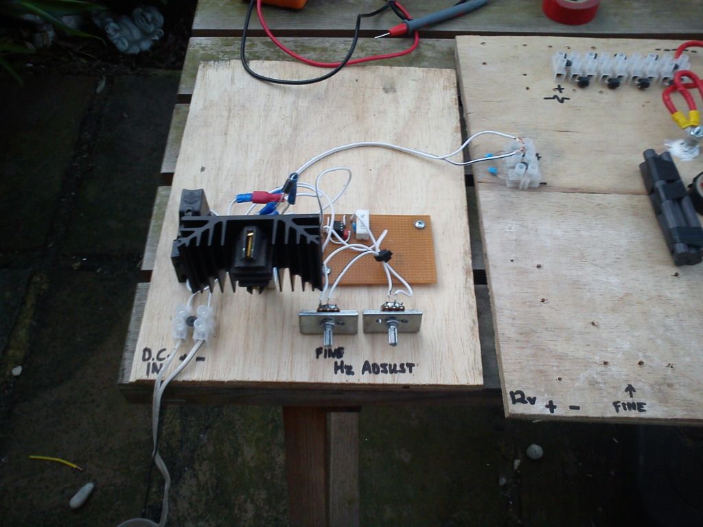
But then things got even more strange. I couldn't get any sparks across the gap unless I held a grounded earth wire CLOSE TO the variable resistors, or unless I had my insulated pliers touching the variable resistors (I wasn't going to tune them with bare hands again!).
This is all very strange. But if I touched the earth wire onto the 47k variable resistor it sparked inside (& smoked), if I touched it onto the 4.7k it made the sparks at the gap stronger.
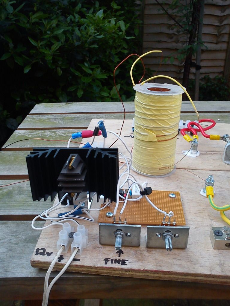
I had 2 grounded earth wires at this time, one was connected to the cold end of the coil.
All very strange
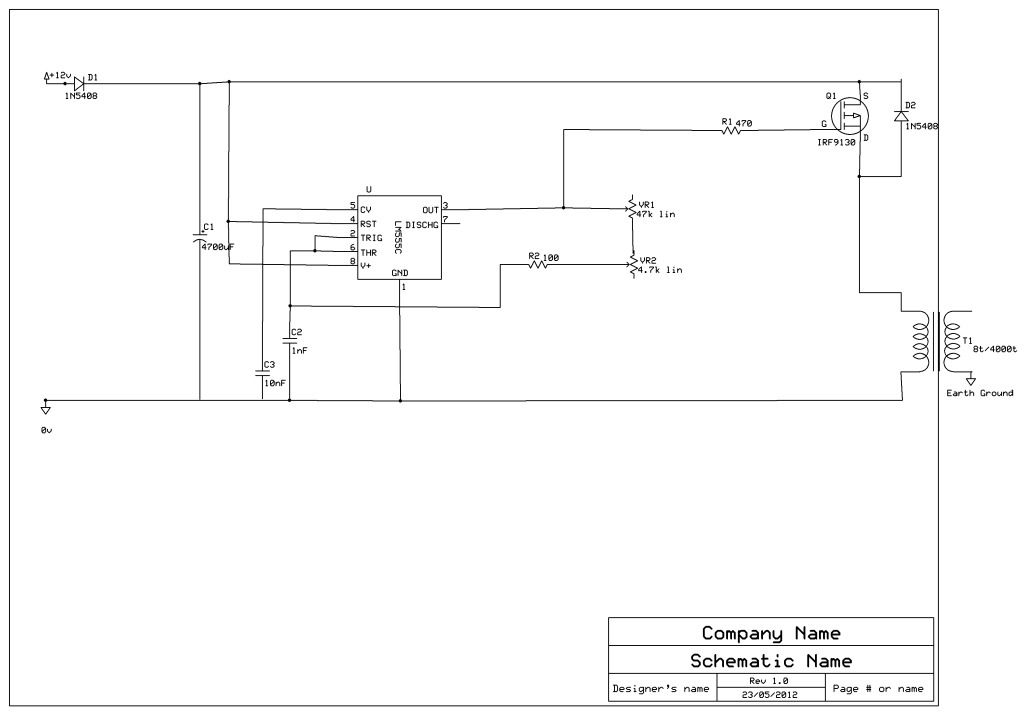
I'm guessing it's feeding back somewhere, maybe there's something wrong with my variable oscillator???
Here's my HV coil......
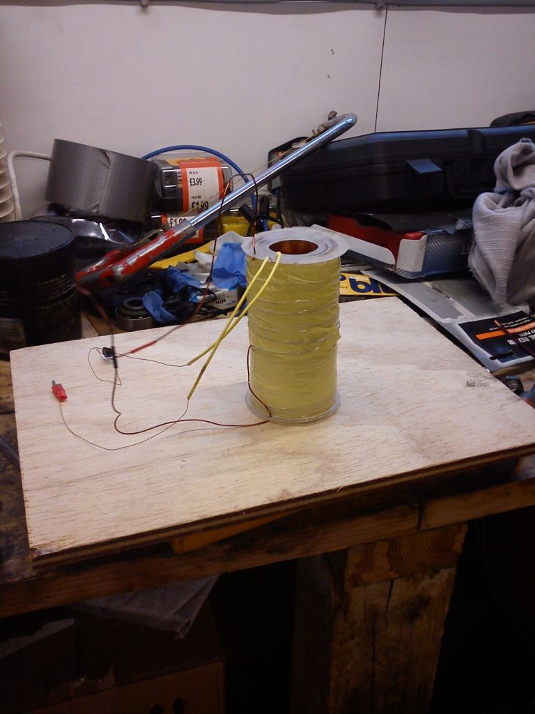
Should I have both HV wires coming out the same end???
I have a 2N3055 transistor, maybe I will just make up a fixed oscillator circuit with the base wired to a 4 turn coil, as per Patrick's other schematic???


Comment