Announcement

Collapse
No announcement yet.

Donald Smith Devices too good to be true

Collapse
X
 
  • Filter
  • Time
  • Show
Clear All
new posts

  • Originally posted by Eng.raied View Post
    thank you zilano
    i will try to build one .
    what type of capacitor you use in your device ?variable?
    do you use capacitor variable or coil variable or frequncy variable to get resonance ?

    thanks in advance
    i use lcr meter and calculate cap. earlier i used home-made caps. then i used variable also with hard disk drive platters and made air capacitors using shaving blades also they worked for my crystal radios. u can use tin foil also. the aim is to have many metal layers insulated with each other and connected in parallel.

    variables are better as they keep u in control of resonance.

    ps: for high voltage use thicker insulater so not to make spark jump across.

    ....

    Comment


    • Originally posted by zilano View Post
      i use lcr meter and calculate cap. earlier i used home-made caps. then i used variable also with hard disk drive platters and made air capacitors using shaving blades also they worked for my crystal radios. u can use tin foil also. the aim is to have many metal layers insulated with each other and connected in parallel.

      variables are better as they keep u in control of resonance.

      ps: for high voltage use thicker insulater so not to make spark jump across.

      ....
      hi zilano
      original device of don smith he use spark in serial .if he use resonance should be used parallel capacitor to get max power output. and he use step up transformer
      please what final and easy circuit you use.

      thanks
      FREE ENERGY = FREEDOM
      raadawad[at]yahoo.com
      eng.raied[at]yahoo.com

      Comment


      • @ boguslaw!

        mini tesla 9v with driver circuit.


        12v Solid State Mini Tesla Coil with Circuit Diagram - YouTube
        Attached Files

        Comment


        • Originally posted by Eng.raied View Post
          hi zilano
          original device of don smith he use spark in serial .if he use resonance should be used parallel capacitor to get max power output. and he use step up transformer
          please what final and easy circuit you use.

          thanks
          Don used pulsed dc to xcite parallel coil cap combination. where as people adapt Tesla type primary oscillator.


          Don method is easiest. when pulsed dc is fed to parallel coil cap combination the LC circuit oscillates at its frequency determined by L and c combination.
          when u r making Don device just Follow the way He did it. there are many ways to harvest power but Don circuit provide the easiest and the best way to learn and make the device. when u learn the basic from this device u will understand resonance and what it can do. u only have to slide in and out the primary to tune secondary. To use power the easy way to use voltage divider circuit and pushpull transistors to drive the transformer. if u have ferrite transformer its much better. one can use iron cored also after the inverting transistors.

          there is similarity between ac adaptor and Don device. but transformer is reversed and made air-cored primary is at lower voltage than secondary. if u understand adaptor circuit u will understand don circuit. its an adaptor circuit with windings of trafo reversed and resonance used.

          if u follow Ac adaptor circuit and understand it then Don circuit is not beyond ur understanding. just keep in consideration of high voltages and resonance.

          PEOPLE DONT HAVE SUCCESS WITH DON DEVICE AS THEY DONT FOLLOW dON SMITH. THEY FOLLOW TESLA AND APPLY TO DON SMITH. WHEN U R USING TESLA TYPE INPUT THERE MUST NOT BE ANY DIODES USED IN PRIMARY CIRCUIT. WHERE AS IF U FOLLOW dON SMITH THEN DIODES MUST BE USED AS SHOWN BY HIM.

          PS: when frequency is not matched or not in resonance then output can be zero. if matched its max!

          rgds

          ....
          a.c ADAPTOR CIRCUIT
          DON CIRCUIT

          rgds
          ....
          Attached Files
          Last edited by zilano; 05-26-2012, 05:39 PM.

          Comment


          • Stop posting with all CAPS.
            You just piss people of as you are shouting.

            You sound like the goverment of Azerbadjan and they for sure have copyright on everything

            Comment


            • Originally posted by zilano View Post
              Don used pulsed dc to xcite parallel coil cap combination. where as people adapt Tesla type primary oscillator.


              Don method is easiest. when pulsed dc is fed to parallel coil cap combination the LC circuit oscillates at its frequency determined by L and c combination.
              when u r making Don device just Follow the way He did it. there are many ways to harvest power but Don circuit provide the easiest and the best way to learn and make the device. when u learn the basic from this device u will understand resonance and what it can do. u only have to slide in and out the primary to tune secondary. To use power the easy way to use voltage divider circuit and pushpull transistors to drive the transformer. if u have ferrite transformer its much better. one can use iron cored also after the inverting transistors.

              there is similarity between ac adaptor and Don device. but transformer is reversed and made air-cored primary is at lower voltage than secondary. if u understand adaptor circuit u will understand don circuit. its an adaptor circuit with windings of trafo reversed and resonance used.

              if u follow Ac adaptor circuit and understand it then Don circuit is not beyond ur understanding. just keep in consideration of high voltages and resonance.

              rgds

              ....
              a.c ADAPTOR CIRCUIT
              DON CIRCUIT

              rgds
              ....
              ok thanks
              concerning the 35khz when i use flyback driver with Capacitor across 8T coil it doesn't change the frequency what i need according to Frequency formula
              the L of 8t coil 69 uH winding on ferrite
              FREE ENERGY = FREEDOM
              raadawad[at]yahoo.com
              eng.raied[at]yahoo.com

              Comment


              • EDE Project

                Hi all

                thank you nutgone`s and all best

                ... continuing

                Stage 3: achieving HV and HF

                When we have a stable dc source, in the next stage we should step up the voltage to approximately 4000V and the frequency above 20KHz

                For driver circuit I use feedback, but I think it would be better to use ZVS /zero voltage switch/

                http://www.energeticforum.com/attach...1&d=1338053672


                best for all balckrobi


                EDE Project II.pdf
                Attached Files

                Comment


                • Originally posted by Eng.raied View Post
                  ok thanks
                  concerning the 35khz when i use flyback driver with Capacitor across 8T coil it doesn't change the frequency what i need according to Frequency formula
                  the L of 8t coil 69 uH winding on ferrite
                  Follow Don way to xcite primary. its Dc to be pulsed by spark gap.
                  u can even use a fwbr and follow Don bertonee circuit. Dc has no frequency and when u feed it to Lc in sudden spurts the coil cap combination oscillates. according to L and c.


                  ....
                  Last edited by zilano; 05-26-2012, 05:46 PM.

                  Comment


                  • Originally posted by zilano View Post
                    Follow Don way to xcite primary. its Dc to be pulsed by spark gap.
                    u can even use a fwbr and follow Don bertonee circuit. Dc has no frequency and when u feed it to Lc in sudden spurts the coil cap combination oscillates. according to L and c.


                    ....
                    now it is very clear
                    the frequency just to get HV pulsed DC from Flyback and the key is the resonance on Pr coil with Se coil to get max power
                    thank you zilano
                    FREE ENERGY = FREEDOM
                    raadawad[at]yahoo.com
                    eng.raied[at]yahoo.com

                    Comment


                    • Originally posted by woopy View Post
                      Hi all

                      some update of my work

                      thank's to Dragon , MrClean and Kajunkreation very good help

                      And of course all contributors

                      good luck at all

                      Laurent

                      charging by induction approach 1.wmv - YouTube
                      Nice job woopy ! keep in mind you can further isolate the "collector" by connecting the AV to an antenna or large mass instead of the ground.

                      Comment


                      • Originally posted by Eng.raied View Post
                        now it is very clear
                        the frequency just to get HV pulsed DC from Flyback and the key is the resonance on Pr coil with Se coil to get max power
                        thank you zilano
                        Exactly. Overunity is in two factors :
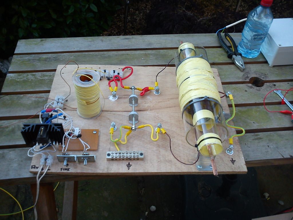
                        - Q factor
                        - Lenz-less transformation

                        We all know that power can be amplified by capacitor , yet Yesla knew he can do the same not just for impulse, because his one impulse produced then continuous oscillation many minutes long.... He described one of his oscillators still working 3 years after ...

                        Comment


                        • Relax

                          Why not just relax and live and let live??

                          Originally posted by janost View Post
                          Stop posting with all CAPS.
                          You just piss people of as you are shouting.

                          You sound like the goverment of Azerbadjan and they for sure have copyright on everything

                          Comment


                          • Shocking!

                            OK, so my build goes on.

                            Today I did my HV module coil, as per Patrick Kelly's eBook, but I'm getting some funny results.

                            I'm powering my HV coil (8 turns pri + 4000 turns sec) via a 12v, 555 based, variable oscillator & a IRF9130 FET (as per Patrick Kelly's schematic, chapter 3 page 63).

                            So, why did I get a nasty shock from my variable resistors when I went to adjust the frequency???

                            My FET is also getting VERY hot, so I've gone for a bigger heat sink.

                            I can't do much more until my new LCR meter turns up & I can start getting some HV caps for resonance tuning. Here's what I have so far.....

                            Comment


                            • Originally posted by woopy View Post
                              Hi all

                              some update of my work

                              thank's to Dragon , MrClean and Kajunkreation very good help

                              And of course all contributors


                              good luck at all

                              Laurent

                              charging by induction approach 1.wmv - YouTube

                              Hi Woopy!

                              great going woopy!

                              fire it to trafo now to light the bulb!

                              good replication!

                              great effort on ur part! admirable!

                              goodluck in all ur tests and builds.

                              rgds
                              ....

                              Comment


                              • Originally posted by nutgone View Post
                                OK, so my build goes on.

                                Today I did my HV module coil, as per Patrick Kelly's eBook, but I'm getting some funny results.

                                I'm powering my HV coil (8 turns pri + 4000 turns sec) via a 12v, 555 based, variable oscillator & a IRF9130 FET (as per Patrick Kelly's schematic, chapter 3 page 63).

                                So, why did I get a nasty shock from my variable resistors when I went to adjust the frequency???

                                My FET is also getting VERY hot, so I've gone for a bigger heat sink.

                                I can't do much more until my new LCR meter turns up & I can start getting some HV caps for resonance tuning. Here's what I have so far.....

                                keep the cold end of ur hv coil earthed to prevent shocks!

                                rgds
                                ....

                                Comment

                                Working...
                                X