 Tweet
Tweet
Originally posted by mr.clean
View Post

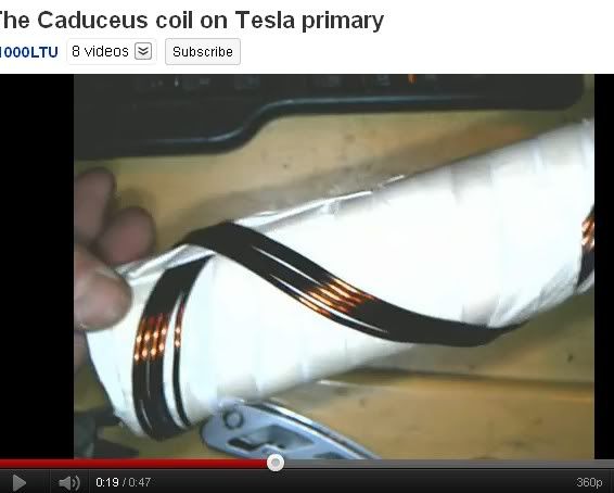
The photo attached below describes.
If you have a transmitter receiver setup, the receiver based on distance from transmitter, field strength, and Q of the receiving tank, you will have a prescribed peak to peak voltage ratio on the receiving end
If your receiver has built in a HV transformer which feeds back to the capacitive element, you in essence make a large virtual antenna. This makes the top load look like a much larger capacitance than it is in reality, thereby interfacing with the transmitter to a greater degree.
If you consider your transmitter to be the earth, or some large outside signal source (ionosphere etc.) then you have really moved towards a free energy antenna.
There are variations which get even more interesting when you involve a delay line, to time the feedback impulses to correctly add to the received impulses.
The capacitor acts like a reflector allowing you to charge the top sphere and reference the ground at the same time both are required.
The second image helps you imagine what is happening. If you imagine the copper sphere (center) charged to 64v, at the doubling of the radius (the small shell next to the copper capacitance) you will see a quadrupling of surface area, 1/4 times the voltage, so you have 16v. Your surface area (related to capacitance) increases by a 4:1, while your voltage decreases by a 1:4, inverses. This is transformer action in the capacitive realm.
As you move further out you see 4 volts on the next shell, and 1 on the next, but in each successive step, you increase the surface area by the same ratio.
So if you have a large wave with a 1v peak to peak fluctuation, you can effect a 64 volt fluctuation in the central sphere radiating the field.


Comment