If this is your first visit, be sure to
check out the FAQ by clicking the
link above. You may have to register
before you can post: click the register link above to proceed. To start viewing messages,
select the forum that you want to visit from the selection below.
Thanks, I have read this many times, but the answer is not there. It give good direction to build the coil and how to pick the natural resonance of the coil, but no info on what to tune the L1 to, or what to match the L2 coil to. Do we just for get about the 35khz from the NST and tune to the natural resonance of L1? Do I use a harmonic of the 35mhz?
Any Help?
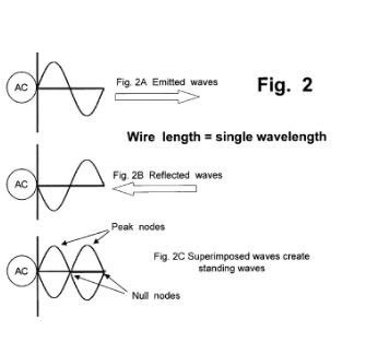
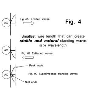
im also confused about the 1/4 wave harmonic and length issue.
ex: 14Mhz is the natural freq, and the 1/4 wave of that is...17.55 ft (i think
**and that is exactly the length of a half of one 10 gauge B&W coil
As far as the primary is concerned... use well proven Tesla rules...
...Don said length, and that is true, but like a guitar, the strings ARE matched by thickness as well as length when tuning.
And small as it is, we are still dealing with a vibration, so audio conception works i think
Tesla was a little more descriptive and i believe he said "the same weight in copper" i dont recall much said of length, just turn ratio and weight
all that being said, if you got a 10 gauge L2, then logically an 8 gauge would be the next size thicker for L1
what im using is 8 gauge wire, 1/4 length of L2 half
(cause its center tapped, we are dealing with one half.
I see the other half as paralled output
So anyway you can measure them, but another thing you can do is weigh the coils before you install them, i have had good luck with that
In the beginner's mind, there are many possibilities.
In the expert's mind there are few.
-Shunryu Suzuki
if we go back and look at the Tesla patents 336,961 and also the 336,962
Tesla was taking power from the outer ends, and calling them.....wait for it
... pos/neg! the center tap was the "auxillary" brush in Teslas stuff,
So Zilano, JoeFr and Blue Serge ARE doing the illustrated patent, by opposite direction coils and the outer ends being pos/neg, rather than center tap neg and outter both positive
It is different from Dons, but undeniably functioning
hehe Blue Serge had 90 watts fused input... and 200 watt bulb almost fully lit... i believe there something interesting there
In the beginner's mind, there are many possibilities.
In the expert's mind there are few.
-Shunryu Suzuki
Hello Zilano, I am also very happy to see you again
Do you think Don`s L1 and L2 coil also have to do with peak nodes of 1/4 standing wave ... as also discribed in this Patent That John Stone mentioned in an earlier post.
Do we have to find the peaks with a small neon lamp . . Do you have more tips on this ..
Well I love to hear from you Zilano all your tips are welcome.
I wish you Love and Light and good Luck with Moray . Utopia Now
still haven't been reading the thread. have been very busy. but have had some time to experiment and clean up the lab. so, i guess i'm not asking for advice at this moment. just an update.
i'm building this circuit right now...
-------------------------
ZVS Flyback Driver | | |
o ---- 3
o ---- 3
| | |
-------------------------
That's a ZVS (Zero Voltage Switching) circuit (by TeraVolt) into a flyback transformer (not shown)... into a gap, caps, and coil all in parallel.
What I expect to see, when I get it all tuned up, is arcing across the gap. Cause when the freq. from the driver/transformer matches the resonant freq. of the caps / coil, the caps / coil appear as infinite impedance.
I may add a ground to give it a source for electrons and to stabilize the voltage, but it should arc with none of that.
I know that because the flyback will drive the gap with nothing else attached.
The trick has been getting the right frequency.
I used a signal generator and an oscilloscope to find the approximate resonant frequency (up to 3 digits of precision) for the L1 cap / coil combination.
I can adjust the freq of the ZVS driver by adding caps across the L1 side of the flyback driver. This works.
But after getting the driver to up to approx. the right freq, with the caps and coil connected, I got nothing.
I think I have been making a tuning mistake. I have been measuring the frequency on the input side of the flyback trafo. And I've probably been taking the freq. with the flyback attached to the caps / coil, which effectively puts it in shunt for all but the resonant freq.
So I am going to tune this up again sometime before the weekend with the high voltage side of the flyback wide open. This is what the cap/coils should look like to the flyback trafo at resonance. Basically just open circuit.
And I'm going to take my measurements off the high-voltage side with a high voltage probe. Already have it and it works fine.
I saw some funky wave forms on the high voltage side while messing around with it this way.
I'm guessing that has to do with the self-resonance of the L2 / flyback.
The flyback trafo I'm using is the one from amazing1.com it's the one that says it's designed for resonant operation.
I'm still not a flyback trafo expert. These are actually somewhat complicated little things in that they "store" flux from the input waveform and deliver it as output with some phase shift and blah blah blah I don't understand. Have read the wikipedia page on flybacks a bunch and still haven't taken the time to really understand.
I'm not sure if this means the flyback is meant to be driven with a "resonant driver" or if it means that the flyback needs to be tuned on both sides with caps for resonance.
I don't think it could be the latter cause I calculated the caps necessary to get the HV side to 36kHz and it was ridiculous. And I get spark out of it at just about any frequency now using the ZVS driver. So that's a big improvement.
Couldn't do that before with my 555 driver circuit or my simple Class A 2n3055 resonant driver circuit.
Anyway... I'm gonna try to tune this up. And if I can't get it to 36kHz, I'm gonna try another flyback. Bought several candidates.
So much of this is just kind of guess, check, and debug. Kindof like working on computers. Looking at inputs / outputs, etc.
Got a breadboard to build up a capacitor array for tuning.
Don't know if this is the right approach, but it's the only one I understand, right now.
Only question is how precise does the resonance need to be? I have a bunch of trim capacitors. But they adjust in the pF. Maybe you get a whole nF out of one, but you would be lucky.
Mostly these seem to be used for UHF / VHF circuits and so looking at all of these components, I'm realizing that 36kHz is really low freq. for radio.
RF amplifiers that cover this range are *really* expensive. THOUSANDS!
Have found some really interesting stuff by Googling "homebrew ham radio", though.
That's the closest tech to this Don Smith device, AFAIK. Oh. And I've ordered a bunch of books from the AARL (American Amateur Radio Relay League).
I used to wonder why Don Smith kept referring to AARL literature and used to think that he was just into amateur HAM radio before he was into "Don Smith" :-). But the technology is quite similar. Lot's to learn from HAM.
I'm choosing 36kHz because it is an integer harmonic of 60Hz, which is what I want out at the end. 600 x 60Hz = 36,000. And frankly, the capacitor array was going to be much cleaner. I just need 8 x .15uF 3kHz capacitors for a total of .3uF.
The tolerance on the caps is like 10% or 5% or something, so I got twice as many as I need so I can mix and match to get as close as possible to .3uF.
So, that's all for now. My big lesson learned is to take measurements off of what actually coming off of the flyback. It's the only way.
I managed to light a 5w bulb with my setup. The thing is when I tried to measure amperage input on my ZVS driver it was above 20amps
My schematic is shown.
Thanks
I think creating the standing wave is exactly what we are after as it creates infinite voltage and zero amperage - cold electricity.
The evidence from all the top shelf guys points towards capacitor turning voltage into amperage.
It makes sense that if a capacitor sees pulsed HV DC then it will perform best.
My own analogy:
The capacitor is the bucket, the HV DC is the rain and the larger the droplets and/or the bigger the bucket, the more kilowatts can be harnessed.
The voltage is at 90 degrees to amperage on a x,y,z axis.
The asymmetrical part being the spark gap.
If I am right then all the circuit diagrams we have been presented with have been drawn slightly wrong on purpose.
PLEASE If you are reading this and can help us, don't hesitate. Time is REALLY of the essence. We can have a Utopia or a disaster, together we can make a difference.
If you don't want to post the information because you don't want to be traced, PLEASE send it to one of the replicators.
For anyone just tuning in, this is a genuine set of devices. Many different ways to skin a cat. Please bear with us at the moment. We are still trying to get ur heads around it all. Some with excellent success.
Please share you experience with replicating this device.
No question is a stupid question. Only the question you don't ask is stupid.
I myself have been testing ignition coils for the device. I'm on my forth and I think I've found a winner. Just waiting for my bits to make a loom, then I'm going to either get a set of pancakes that have the same inductance as capacitance, or skip that and go straight for a 3 plate capacitor.
Here is the link to the article he wrote. January 29
There is also a plug in for Google earth hence you can check to see Steven Marks and the others location.
Patrick Kelly, it would be good to see if there are any links to the others in your pdf who have reported success.Kapandanze,Moray, etc.
Just to say that Joe in his article did find some correlation between location and the successes of the people using his Transmutation Techniques.
I noticed the business of resonance was key to transmutation in his theories.
Zilano and others have echoed, follow Don and maybe these special locations mentioned by Don may be a big factor.
Remember the info that places like water falls and grotto being areas of high negative ion concentrations? Wonder if waterfalls correlate to the strong purple areas on the magnetic field maps? Could we try for Niagara Falls eh?
Hey Zilano, what do you think about this location theory? Could you check your location for us please.Just let us know if you fall in the strong purple area.
Thanks.
Best regards,
Ged
Thanks so much Ged! I've been trying to find that web site again for a couple months now. It seems Zilano thinks location may not be important for this device and I tend to think she is correct but I know some other things it may be important for. It would appear Don lived in a good strong zone although I need to double check his actual address which I've got somewhere around here. The info I did find is based on his phone number and that puts him in a very good zone.
still haven't been reading the thread. have been very busy. but have had some time to experiment and clean up the lab. so, i guess i'm not asking for advice at this moment. just an update.
i'm building this circuit right now...
-------------------------
ZVS Flyback Driver | | |
o ---- 3
o ---- 3
| | |
-------------------------
That's a ZVS (Zero Voltage Switching) circuit (by TeraVolt) into a flyback transformer (not shown)... into a gap, caps, and coil all in parallel.
What I expect to see, when I get it all tuned up, is arcing across the gap. Cause when the freq. from the driver/transformer matches the resonant freq. of the caps / coil, the caps / coil appear as infinite impedance.
I may add a ground to give it a source for electrons and to stabilize the voltage, but it should arc with none of that.
I know that because the flyback will drive the gap with nothing else attached.
The trick has been getting the right frequency.
I used a signal generator and an oscilloscope to find the approximate resonant frequency (up to 3 digits of precision) for the L1 cap / coil combination.
I can adjust the freq of the ZVS driver by adding caps across the L1 side of the flyback driver. This works.
But after getting the driver to up to approx. the right freq, with the caps and coil connected, I got nothing.
I think I have been making a tuning mistake. I have been measuring the frequency on the input side of the flyback trafo. And I've probably been taking the freq. with the flyback attached to the caps / coil, which effectively puts it in shunt for all but the resonant freq.
So I am going to tune this up again sometime before the weekend with the high voltage side of the flyback wide open. This is what the cap/coils should look like to the flyback trafo at resonance. Basically just open circuit.
And I'm going to take my measurements off the high-voltage side with a high voltage probe. Already have it and it works fine.
I saw some funky wave forms on the high voltage side while messing around with it this way.
I'm guessing that has to do with the self-resonance of the L2 / flyback.
The flyback trafo I'm using is the one from amazing1.com it's the one that says it's designed for resonant operation.
I'm still not a flyback trafo expert. These are actually somewhat complicated little things in that they "store" flux from the input waveform and deliver it as output with some phase shift and blah blah blah I don't understand. Have read the wikipedia page on flybacks a bunch and still haven't taken the time to really understand.
I'm not sure if this means the flyback is meant to be driven with a "resonant driver" or if it means that the flyback needs to be tuned on both sides with caps for resonance.
I don't think it could be the latter cause I calculated the caps necessary to get the HV side to 36kHz and it was ridiculous. And I get spark out of it at just about any frequency now using the ZVS driver. So that's a big improvement.
Couldn't do that before with my 555 driver circuit or my simple Class A 2n3055 resonant driver circuit.
Anyway... I'm gonna try to tune this up. And if I can't get it to 36kHz, I'm gonna try another flyback. Bought several candidates.
So much of this is just kind of guess, check, and debug. Kindof like working on computers. Looking at inputs / outputs, etc.
Got a breadboard to build up a capacitor array for tuning.
Don't know if this is the right approach, but it's the only one I understand, right now.
Only question is how precise does the resonance need to be? I have a bunch of trim capacitors. But they adjust in the pF. Maybe you get a whole nF out of one, but you would be lucky.
Mostly these seem to be used for UHF / VHF circuits and so looking at all of these components, I'm realizing that 36kHz is really low freq. for radio.
RF amplifiers that cover this range are *really* expensive. THOUSANDS!
Have found some really interesting stuff by Googling "homebrew ham radio", though.
That's the closest tech to this Don Smith device, AFAIK. Oh. And I've ordered a bunch of books from the AARL (American Amateur Radio Relay League).
I used to wonder why Don Smith kept referring to AARL literature and used to think that he was just into amateur HAM radio before he was into "Don Smith" :-). But the technology is quite similar. Lot's to learn from HAM.
I'm choosing 36kHz because it is an integer harmonic of 60Hz, which is what I want out at the end. 600 x 60Hz = 36,000. And frankly, the capacitor array was going to be much cleaner. I just need 8 x .15uF 3kHz capacitors for a total of .3uF.
The tolerance on the caps is like 10% or 5% or something, so I got twice as many as I need so I can mix and match to get as close as possible to .3uF.
So, that's all for now. My big lesson learned is to take measurements off of what actually coming off of the flyback. It's the only way.
Cheers!
:-)
right on
and Don had also been a fan of ...the cystal set radio...
pick up signal with no battery.... hmm ... hinthint
In the beginner's mind, there are many possibilities.
In the expert's mind there are few.
-Shunryu Suzuki
The capacitor is the bucket, the HV DC is the rain and the larger the droplets and/or the bigger the bucket, the more kilowatts can be harnessed.
The voltage is at 90 degrees to amperage on a x,y,z axis.
The asymmetrical part being the spark gap.
If I am right then all the circuit diagrams we have been presented with have been drawn slightly wrong on purpose.
PLEASE If you are reading this and can help us, don't hesitate. Time is REALLY of the essence. We can have a Utopia or a disaster, together we can make a difference.
If you don't want to post the information because you don't want to be traced, PLEASE send it to one of the replicators.
For anyone just tuning in, this is a genuine set of devices. Many different ways to skin a cat. Please bear with us at the moment. We are still trying to get ur heads around it all. Some with excellent success.
Thanks so much Ged! I've been trying to find that web site again for a couple months now. It seems Zilano thinks location may not be important for this device and I tend to think she is correct but I know some other things it may be important for. It would appear Don lived in a good strong zone although I need to double check his actual address which I've got somewhere around here. The info I did find is based on his phone number and that puts him in a very good zone.
Hi Ewizard,
I saw Zilano's response.Now since I do not have a working or experimental device and zero experience with such devices I can only hypothesize from existing models.
I specifically used words such as "some of Don devices" .I recall at one conference they did mention location as a factor in some of the devices.I also recall Patrick speaking about the plasma device as location sensitive.When I have the time I will fetch the exact references, as I might be mistaken.Anyway, we might still be onto something as you have already found that Don was in a good area.Those are the facts.Don must have thought it important to mention such maps.Even going to the extent of explaining it during an interview.Maybe he really meant to explain the charges the earth holds.Now this was Don himself, holding and explaining these maps.Again maybe, just maybe, I might be reading too much into it.Until I have a device of my own.I leave it all up to speculation.
I remember reading the Celestine Prophecies Tenth Insight and seeing mention of places of power been used as the location of these resonant devices.Fact or fiction.Time will tell.
Remember that at over 100 pages of good stuff, no third party is able to show a working 10kW device or even a 1 kW device for that matter.
Hence as researchers, until we have a working device ,preferably built by our own hands, can we truly confirm some of the theories postulated thus far.
 Tweet
Tweet


 and I see you have hit the ground running as usual.Words can't say enough...
Comment