 Tweet
Tweet
Originally posted by dragon
View Post
-
Hi, i know it's a good idea, but in my case ( Hydro QC ) if you this kind of thing they're gonna say that you correct the power factor from their network and we cannot do this, but if you have a stand alone system, it's a very good idea, btw, i'm gonna test your circuit RLC (Did you use a battery and invertor ??? ) thanks -
frankidel, I've had various success's using inverters, it works best with a pure sine wave. The modified sine wave inverters are very difficult to match. I don't think that is the overall solution but it does work.Originally posted by frankidel View Post
MrClean, I did post a video a year ago showing a small motor with a poor matching cap, even with a poor match it still cuts power by around 60% going from 18 watts to 8. Add a light bulb in line and you basically have the same thing with mechanical output as a bonus.Comment
-
Condenser Rules
Hi folks !
In my country we use to this very day, yet the exact word
Kondesator aka condenser.It makes more sense this way !!!
the "new" name given to these beasts gives the idea that you have
something which is limited as to what power you can use them for + adds
loads of confusion to all fresh minds on field of electric study as to give the wrong
impression the ol`good guys of old times did not "exactly" knew what they
were observing
Don L.Smith did not recomended batteries as a good storing device the
reason is their short range of life which leads us to more expenses the long run.
In Don`s devices the capacitors were almost the key components.
 << BP Ultimate + Shell-V Power + Allies (opec) = the Ultimate Power Aligators to Suck People`s Blood !-! >>
Comment
-
Here are some links for power factor correction and inverters.
This link seems solid.
Power Factor Correction (Power Factor Compensation) technology and Calculations
This text below is from the above link.
If I was to put the wrong size capacitors on the output of my home madeSupply Resonance.
Capacitive Power factor correction connected to a supply causes resonance between the supply and the capacitors. If the fault current of the supply is very high, the effect of the resonance will be minimal, however in a rural installation where the supply is very inductive and can be a high impedance, the resonances can be very severe resulting in major damage to plant and equipment. Voltage surges and transients of several times the supply voltage are not uncommon in rural areas with weak supplies, especially when the load on the supply is low. As with any resonant system, a transient or sudden change in current will result in the resonant circuit ringing, generating a high voltage. The magnitude of the voltage is dependant on the 'Q' of the circuit which in turn is a function of the circuit loading. One of the problems with supply resonance is that the 'reaction' is often well removed from the 'stimulus' unlike a pure voltage drop problem due to an overloaded supply. This makes fault finding very difficult and often damaging surges and transients on the supply are treated as 'just one of those things'.
To minimize supply resonance problems, there are a few steps that can be taken, but they do need to be taken by all on the particular supply.
1) Minimize the amount of power factor correction, particularly when the load is light. The power factor correction minimizes losses in the supply. When the supply is lightly loaded, this is not such a problem.
2) Minimize switching transients. Eliminate open transition switching - usually associated with generator plants and alternative supply switching, and with some electromechanical starters such as the star/delta starter.
3) Switch capacitors on to the supply in lots of small steps rather than a few large steps.
4) Switch capacitors on o the supply after the load has been applied and switch off the supply before or with the load removal.
supply converter the voltage at the output could go to double the normal
output voltage and the converter could draw twice as much current at
standby with no load.
...
This one says power factor correction in the home is a waste of money.
KVAR Power Factor Correction in the Home is a Scam
I can't say I fully understand it yet, but I can say one think all inverters are
not created equal, two similar looking inverters can have different circuitry
and features.
Do people check to see if adding capacitors to the input of a transformer from
the grid causes a higher idle power draw for the transformer ? And I'm talking
about at the power company meter not the consumers kWH meter at the transformer.
From Jaycar
http://www.jaycar.com.au/images_uploaded/inverter.pdfUNDERSTANDING & USING DC-AC INVERTERS
CheersLast edited by Farmhand; 03-04-2012, 01:56 AM.Comment
-
I'm currently doing a project with 3 > 480V 500KVAR Banks. Normally these are installed with power factor sensing that controls a bank of switching contactors that turn on/off smaller cap banks as needed based on the PF set point. In the above case, there are 10 steps @ 50KVAR/step.Originally posted by Farmhand View Post
On smaller motors, the caps are mounted on the load side of the motor controller and are taken out of the circuit when the motor is switched off.Comment
-
PFC is simply a stepping stone to learn about reflective energy. Here is a quick video of a really basic mini set up showing you can take a resistive load and turn it into an inductive load and remove most of the losses.
In the video the bulb is in series with a motor coil and the cap is parallel connected to the load. It starts out driving a 15 watt 120v bulb with 11 watts, then when the cap is connected it drops to 3 watts with no noticeable change in light intensity. I connect the cap and disconnect it a couple times... Sorry about the quality, my camera is old....
windfilter's Channel - YouTube
If you can reflect the energy back to the input then the input requirement is much lower. The amount that is reflected is based on the load - primarily the heavier the load the more gets reflected. This is where shorting coils starts to make more sense, this is as loaded as they can get and most of the energy can be reflected back to the primary.Last edited by dragon; 03-04-2012, 02:57 AM.Comment
-
As we know terms are some very fragile vehicles in order to transport thoughts. Everybody interprets them conforming his own experience.Originally posted by Peculian View Post
So what does a name say? What says John to us? Everybody knows another set of John's with different properties. Nobody can describe me by calling my name.
1. Capacitor suggests that we can store there energy and get it out at will and as we can make or buy components with different capacity to dto that we call it "capacity"
2. I understand as "Kondensator" (yes it is my native languge as well) the notion that electrons can be condensed, compressed there like air. We know that this model of thinking is not correct. (see MIT video)
3.Others think of "condense" to be water droplets evading from seemingly nothing and gathering in air (fog) or on the window glass. That notion hits the target more precisely.
Anyway all of these notions are somehow correct but cover a small facet of the truth only. The name was defined conforming the main use of it's property.
So let's depart from this narrow tunnel view to one property at a time and widen the notion to all known properties:
- We can get energy out if we put it in before (but no condensed electrons involved)
- Take a charged capacitor apart and there is no charge left, no field left. Add the components and the charge kills you. We get a deep view into a deep dark well - and understand nothing
- We have a strange displacement current when charging it
- It can be conditioned with time delay (like coils or flywheels) in order to perform an additional power output
- It can be operated highly asymmetrically (see Utkin)
- Electrons can't be the base of charge. They might be the trolley helping to get energy into the store and getting it out again. Trolleys must not be confused with the goods they carry.
- The energy is never transprted by flowing electrons (no "condensed" electrons available) but electrons are being energized by the source (Bearden) and the energizing front moves by speed of light - but never do electrons do this.
- Our electic scinece begins with it's main enemy - the perpetually stressed "perpetuum mobile". Every charge emits a field into the space and the field contains energy. But the charge does not deminish!!!!! It stays there and emits energy. Turtur shows that if we calculate the whole propagating field contained in the space affected - there is a certain amount of energy missing - increasing with time / space . So the energy flows back into the ???? (use whatever term you feel to be appropiate) and comes back via the portal called "charge". It is a closed circuit.
So what is it's description, it's name? It is a portal to an unknown very interesting and demanding world.Last edited by JohnStone; 03-04-2012, 10:20 AM.Experts spend hours a day in order to question their doing while others stopped thinking feeling they were professionals.Comment
-
Two kinds of resonance
This patent deals with two kinds of resonance: Lamda/4 and LC. It is very educational and gives some light on resonance types / pancake coils and Don's circuit.Experts spend hours a day in order to question their doing while others stopped thinking feeling they were professionals.Comment
-
Blue Serge and Nolanmenne are both using the HV ouputs with HV diodes with the the gas discharge tube in parallel after the diodes.Originally posted by mr.clean View Post
The capacitor is in series with the L1 coil and they are both in parallel with the spark gap.
My observation (without experiment yet) is that this is only one capacitor off a hairpin circuit which as we know forces resonance and makes cold electricity / scalar / LMD.
We are trying to make a mirrored primary correct?
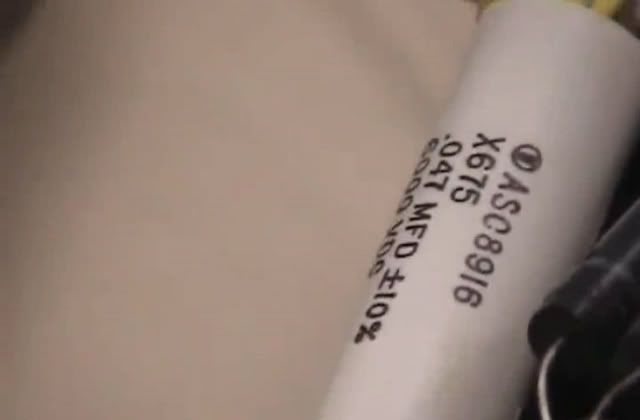
Here is a close up of the L2 capacitor.Originally posted by mr.clean View Post
After listening to all of Don's videos that I can find here is what I heard.
The L1 capacitors were ordered from Cornell Dubilier and were rated at 10kv and 0.5uf each.
Contact Us - Directory By Department - CDE.com
However the capacitors in the picture are manufactured by Custom Electronics.
How to Contact Us | Custom Electronics, Inc.
The are rated at 0.1uf each and rated at 4000v.
It is very clear to me that Don wanted to disclose everything after his dreams of getting this to market were squashed again and again by special interests.
He had friends in high places and clearly they let him build from his imagination many different devices until he laid his last golden egg.
This must have been on the proviso that he never disclosed exactly how to build a device.
Just like Tesla and in his footsteps, Don scattered the truth right, just like a puzzle right before our eyes. Even saying 'the smart ones will figure it out'. He blantantly used a different manufacturers capacitors because knew someone would pick up on it eventually.
Now I'm very happy to be proved right or wrong. I just wanted to share my observation.
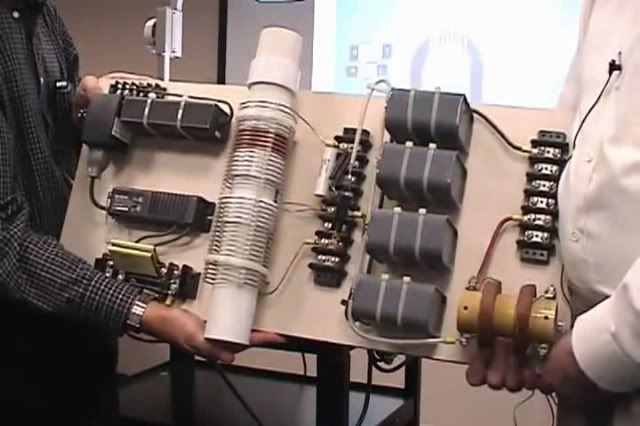
Here are some more photos that you may like to see.
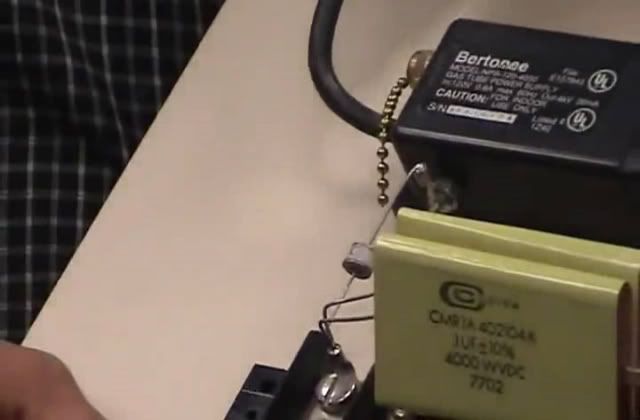
Don also said the NST was custom manufactured by Bertonee.
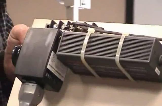
The diodes are 25kv and were custom manufactured by Varo.
Originally posted by mr.clean View Post
The secret is in this. The coil is the 3 and the CW and CCW are the 6 and 9.
Don also said look at diodes, capacitors and coils. The voltage is in the length and the amperage is in the width.
If the capacitor is in parallel with both negative lines, does that mean it is in series because they are both negative???Originally posted by mr.clean View Post
Once we debunk the main board Don shows we will move forward very quickly.
If Don had the NST custom made then would having the primaries wound in CW and CCW make any difference?
I believe it would as I keep blowing 3 amp fuses in my driver when I'm experimenting.
I assume that if the primary windings were in CW CCW fashion then there wouldn't be any back emf.....???Comment
-
The "dissectible Leyden jar" myth
Leyden jar - eNotes.com Reference
The "dissectible Leyden jar" myth
A popular but misleading demonstration with a Leyden jar involves taking one apart after it has been charged and showing that the charge is stored on the dielectric, not the plates. The first documented instance of this demonstration is in a 1749 letter by Benjamin Franklin.[6] Franklin designed a "dissectible" leyden jar, shown at left, which was widely used in demonstrations.
The jar in the demonstration is constructed out of a glass cup nested between two fairly snugly fitting metal cups. When the jar is charged with a high voltage and carefully dismantled, it is discovered that all the parts may be freely handled without discharging the jar. If the pieces are re-assembled, a large spark may still be obtained.
When not properly explained, this demonstration promotes the myth that capacitors store their charge inside their dielectric. This erroneous belief was taught in schools throughout the 1800s, and is still sometimes encountered. However this phenomenon is a special effect caused by the high voltage on the Leyden jar.[7] In the dissectible Leyden jar, charge is transferred to the surface of the glass cup by corona discharge when the jar is disassembled; this is the source of the residual charge after the jar is reassembled. Handling the cup while disassembled does not provide enough contact to remove all the surface charge. Soda glass is hygroscopic and forms a partially conductive coating on its surface, which holds the charge.[7] Addenbrook (1922) found that in a dissectible jar made of paraffin, or glass baked to remove moisture, the charge remained on the metal plates.[8] Zeleny (1944) confirmed these results and observed the corona charge transfer.[9] In capacitors generally, the charge is not stored in the dielectric, but on the inside surfaces of the plates, as can be seen from the fact that capacitors can function with a vacuum between their plates.[10]Comment
-
Tesla said that electrons exists only in pure vacuum. I think electrons are simple waves like other particles with a twist in space called spin which makes them small magnets (vide Ed Leedscalnin). The have frequency which is different then AC frequency, it is that frequency which converts them into standing wave when hit by boundary. So first there is relaxation time when charge flow is not divided into standing wave and then it is reflected first time and standing wave occur and electrons appear as a quantum states of this wave reflected by boundary and changed by crystal structure of atoms.
It is to be proved if on one side of DC power supply like battery there is this wave flowing as voltage and on the other side opposite wave forming then current but I think that concept based one Ed Leedscalnin may be hot topic of the future.
Comment
-
Don wanted us to connect modified NST and secondary arrangement and conclude that we have to have CORE inside secondary to make it work.Originally posted by soundiceuk View Post
Then connect that with schematic of Tesla patent and bifilar transformer device Don showed and you have what Tesla sentence means. A coil looking like 3 when one part is wound like 6 and second like 9.Comment
-
Power Control
This is a link to a 1920�s Fisher Diathermy machine / Tesla Coil. I find it interesting because it uses an inductor to control the power factor before it is sent to the step up coil.
Fischer Diathermy: Narrating and Exploring a 1920's Tesla Coil - YouTubeComment
-
I have one just like it.Originally posted by ZeroMassInertia View Post
Half of the Answer is knowing the right QuestionComment
-
Seg
Hi,Originally posted by African View Post
It seems to me that the image is a mock up.
Have a look at the video though.Wanted to hear from others if the theories shown using 3D animation is valid according those discusses here.
GedComment
Comment