 Tweet
Tweet
Originally posted by boguslaw
View Post
-
The ground lead connected and disconnected in the - is that comparable to the spark doing the switching automatically?Experts spend hours a day in order to question their doing while others stopped thinking feeling they were professionals. -
I remember Utkin writing that in Don's demonstration there should be 3 plates!!!Originally posted by dragon View PostExperts spend hours a day in order to question their doing while others stopped thinking feeling they were professionals.Comment
-
The d.Smith was showing basic principle about capacitor placed in middle of spark gap.Originally posted by JohnStone View Post
And actually if you wind capacitor roll yourself, you can have up to 4 wires connected (2 in center 2 outside). This is where it becomes interesting when capacitor is being used as coil as well...
P.S> Anyone ever had Tesla Coil still running for few seconds after primary gets disconnected from oscillating circuit? Having interesting effect here when Tesla coil is on PVC pipe and inside of transformer oil.Comment
-
this is cool i'll try thisOriginally posted by a.king21 View PostIn the beginner's mind, there are many possibilities.
In the expert's mind there are few.
-Shunryu SuzukiComment
-
-
Originally posted by kajunkreations View Post
Cap should go across the NST supply AFTER diodes.
Cap should be tuned to NST frequency and NOT L1.
Spark gap should be in series with coil primary and just prior to it.
Primary must NOT be cap tuned.
Gap can be quenched using 2 small round neos each side of spark.
Your coil primary too many turns.
Initial spark frequency will be fundamental in the high Khz range more often but not always at NST frequency.
Most of Tesla's spark gaps operated around 50khz but the abrupt interrupt harmonics were captured to low Mhz.
Secondary coil will do the conversion and capture harmonics in the Mhz range IF its working correctly.
NST should be voltage tuned using a variac as Don Smith to adjust power amplitude where sine peaks are only JUST enough to jump the spark gap without shutting down NST into overload condition. GDT same conditions apply!
Some NEW NST's wont allow for amplitude changes without shutting down. Requires other methods to TAME them down perhaps high inductance chokes or small series cap.
Secondary coil must operate in extreme VSWR condition where center NODE is tapped in the dipole.
Better to make Tesla coil FIRST to understand principle of EHT secondary tuned to standing wave condition using large inductance. See Wesley latest tube/valve amp tesla circuit.
Lighting a 50w lamp from 60 watt NST can hardly be a claim to OU!
Let me know when you manage 5kw!
NOTE: Voltage gain is NOT a product of coil ratios in scaler operation but a factor of coil Q. Thus L1 could be 10 turns and L2 could be 30 turns. Ratio 1:3 but voltage could easy be 80 times higher on the ends of L2Last edited by bolt1; 02-25-2012, 11:53 PM.Comment
-
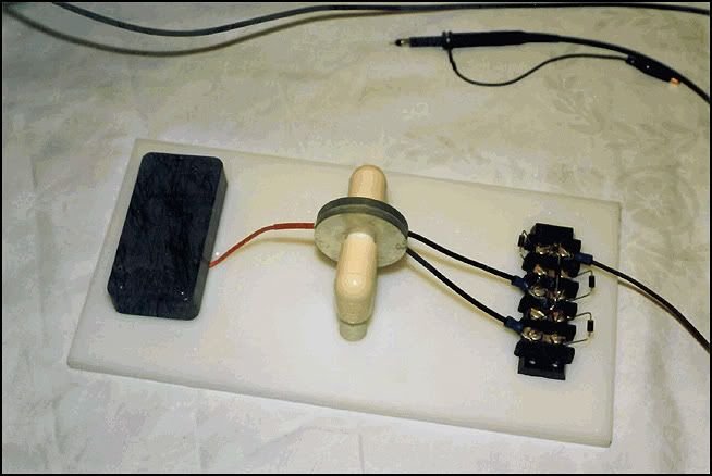
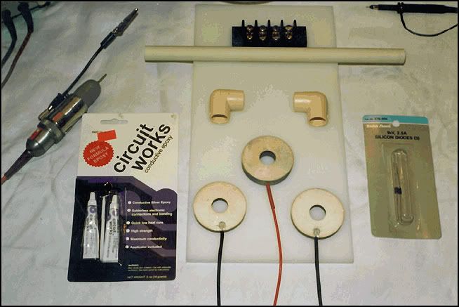
More Genuine Pics

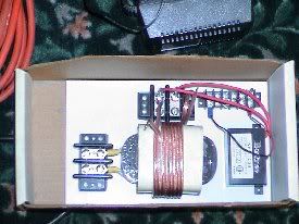
I think that's the lot now, apart from the pics of Don himself.
Please add to your archives!
Comment
-
Hello everyone + thanks everyone contributing
@kajunkreations
You have a nice setup there.
Now let me tell what I personally see you should make changes (maybe ?)
First off,in your primary you have too much turns as Bolt1 pointed you,
than I add to that your "primary" should be much thicker than the one you`re
using there.For example see what size are the NST output wires are of
I believe you got the idea.Maybe your secondary should be a bit thicker too
in order to attract some more amps in your secondary part circuit,coz the secondary
somehow "absorbs" what primary circuit gives + some ambient energy into the circuit.
Something that might help aswell control the whole thing there is to have variable
voltage at input of NST or NPS btw.. experimenting will lead you at right conditions
for your overall circuit set.
Carefully see and read Don`s work + work done by some respected members here
as in example Mr.Clean`s simple setup (see backpages of this topic + some videos too)
Best thing for you is that you are hands-on active in that research -
good for you .Wish you the best results and please be safe first.
@ a.king21 >C'mon GUYS and gals... This has got to be a big clue...
Help me here.... <
Maybe this might not be of that great help but anyway have a second look at this

I am still trying to compile pieces as to get as much of a good understanding
in this one.")
@Seeker2011
Can you please give more details about your setup ? Maybe others here may help you
with some insights. It is difficult to succeed on the free energy arena, especially
when someone is alone trying to get the hangs how these sort of things work together
to give people good promising results and as paradoxal as it might turn out
to be, for something to really work without much hassle things should be kept
as simple as possible allowed.
Peace << BP Ultimate + Shell-V Power + Allies (opec) = the Ultimate Power Aligators to Suck People`s Blood !-! >>
Comment
-
Isn't the capacitor supposed to be in parallel and the spark gap in series for OU bell waveform?Originally posted by Guruji View PostComment
-
Originally posted by bolt1 View Post
Bolt, Thanks for the info, I do realize that my setup is a copy of Don Smiths. It is more like the setup Blue Surge was using. I plan on doing all kinds of different experiments.
I also know that lighting a 50 watt bulb with an NST is not OU.
I have researched this for some time,watched every video there is,read every PDF file I could find, lurked on forums for 2 years and completely understand the theory.
So please dont make a comment like that again. It seems we need all the researchers we can get, dont run them off by making assumtions about what one knows or doesnt know.
Thanks
NolanComment
-
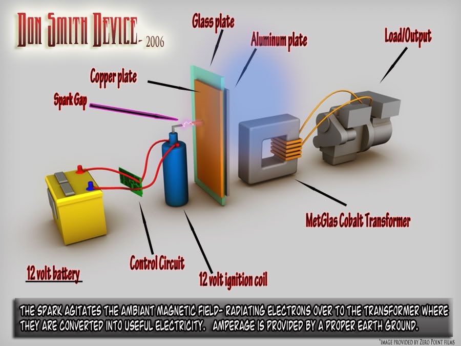
The Final Golden Egg (Is it?)
I can't imagine this getting smaller. Lets wait for the next guy to simplify this.
 - Donald Lee Smith -
Also from Don "JAPANESE SELF POWERED ENERGY RODS - - - Simply one Rod
being of Carborundum and One Being of Piezo material."
And another:
- DON SMITH ENERGY GUIDE -
SOURCE MUST BE OPEN , AND UNIVERSALLY AVAILABLE.
THIS EXCLUDES SOURCES WITH LIMITED OR PARTIAL ACCESS.
THIS NARROWS THE FIELD TO THE RESONATE ELECTRONS SPIN SOURCE.
AT THIS POINT USEFUL RADIANT ENERGY IS ACCESSIBLE TWO BASIC SOURCES, BEING ELECTRO AND MAGNETIC FLUX. ELECTRO IS SUBJECT TO OHM�S LAW AND RETURNS TO THE AMBIENT BY A HEAT DEATH.
MAGNETIC IS FULLY AMPLIFIABLE AS SEEN IN AUDIBLE SOUND AND RADIO FREQUENCIES. RADIO FREQUENCIES BECOME ACCESSIBLE THROUGH HETERODYNING. THEREFORE THE HUGH POTENTIALS OBSERVED FROM
TESLA COILS, GAUSS METERS, PLASMA TUBES AND SPARK GAPS ARE OPEN SOURCES WHICH ACCESS THE UNIVERSE�S AMBIENT ENERGY, WHICH IS EVERYWHERE PRESENT.
THE MAGNETIC COUNTERPART OF AMPERAGE AND RESISTIVITY ARE USED BY SPECIAL INTEREST IN THEIR EFFORT�S AT HIDING THE TRUE SOURCE OF ALL ENERGY.
TWO INEXCUSABLE OMISSIONS ARE WRITTEN OUT OF THE TEXT BOOKS. FIRSTLY, IN MAGNETIC SYSTEMS POTENTIAL AND AMPERAGE ARE EQUAL. MAGNETIC FLUX SPEED IS GREATER THAN VISIBLE LIGHT SPEED.
SECONDLY, THE MAGNETIC EQUIVALENT OF NEGATIVE RESISTANCE IS HIDDEN, BEING THE INCREASE OF MAGNETIC PERMEABILITY. MEASUREMENT METHODS USED BY PHYSICS ARE HIGHLY SUSPECT.
OFF THE SHELF COMPONENTS TO THE EXTENT POSSIBLE.
EXCLUDE MOVING PARTS TO THE EXTENT POSSIBLE.
ABSOLUTE REQUIREMENTS ARE : A BROAD BAND DIGITAL HIGH RANGE GAUSS METER, DUAL TRACE OscilloScope, DIGITAL HIGH VOLTAGE - FREQUENCY METER.
OTHER ITEMS AS REQUIRED .
Donald L. Smith, Registered Professional Engineer,
Phone / Fax 903 989 2821
2009 FM 815
Trenton, Texas 75490, U.S.A."
Many thanks Google!
Comment
-
Hi Nolan, Good to see you jumping in and doing some experiments.Originally posted by kajunkreations View Post
Does your NST have a dedicated ground lug/connection ? I have a small NST
too which i'll be trying to use soon but mine is 240 input.
I don't agree with some of what bolt has said.
1. The primary cap should be sized to make the L1 vibrate at the resonant
frequency of the secondary coil.
But you appear to have a step down setup. I haven't though much about
what is needed with that, but it would seem that the primary the many turns
coil should be made resonant at the same frequency as the NST, (not easy)
What needs to happen is the NST needs to make the L1-primary ( many turns coil)
vibrate at it's resonant frequency, then the L2-secondaries ( few turns coils)
need to be made to resonate with the L1 to get good output from them.
Tuning caps would be necessary to achieve that in my opinion.
Exciting the many turns coil directly with lower frequency cap discharges like
we would a primary coil might not work too well. To get a resonant step down the many
turns coil needs to be excited at it's resonant frequency by another resonant
transformer in regular step up mode working at the same resonant frequency
as the step down one.
I just don't think it will work directly in step down from the NST like that very well.
This is another case where I must disagree with Zilano.
CheersComment
-
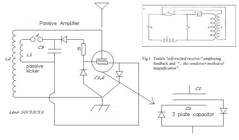
Soundiceuk
My money's on this circuit or a variation of it. This is the first circuit that makes sense to me. It creates a regeneration circuit, which should auto resonate. Also a standing wave is created between the earth ground and the avramenko. This is a self oscillator. I suspect the earth wire has to be a 1/4 wavelength. The avramenko will certainly charge the capacitor from earth ground based on the capacitor input voltage from the circuit.(see Lodge). In other words the resonance between the earth and the capacitor will duplicate the watts on the capacitor. The regeneration circuit should act like a feedback accoustic howl increasing the power which should be duplicated from the earth ground standing wave.Originally posted by soundiceuk View Post
Where did you get the circuit from? I would like to see the original please.
I suggest we go with this. It's simple enough. Very interesting. Thanks for posting.
Comment
-
a.king21: That was another one I posted a bit ago. I was playing around with some of the tesla receiver circuits in the Colorado springs notes. All you need is a signal.Comment
-
@Peculian
Not much more detail to give right now. I have calculated a tank circuit that should resonate at 3.56Mhz. I was wondering what rate I would have to have on the spark gap to keep that going. Should it fire 10 times a second, 100 times, 1000, 10,000? I'm just trying to put something together right now.
Thanks for the help.Comment
Comment