Announcement

Collapse
No announcement yet.

Donald Smith Devices too good to be true

Collapse
X
 
  • Filter
  • Time
  • Show
Clear All
new posts

  • Originally posted by dragon View Post
    Those scrap yards make me feel like a kid in a toy store ! Great find. The biggest problem I've found with the MOT's is they need a voltage much higher than they can handle to bring the output up to a useable level. Good for testing but I don't believe they would handle a final design. A nice small 15kv pole pig would definitely fit the bill or something custom made and oil filled.

    There are some interesting video's on youtube showing how the distribution transformers are made. Wouldn't take much to make up smaller units for our purpose.

    I fully agree that the output is almost more important than the input circuit. Charging the caps is a fairly easy task, dealing with the HV output is considerably more challenging.
    Yeah they are prone to insulation damage, but I use two, I anti parallel the primaries the two cores are joined and grounded along with one end of each secondary (which are already joined to the core), then there is over 4000 volts between the two HV actives. They can fire a spark gap quite wide and fast with anything from 60 Hz to 360 Hz but at the higher frequencies there is less power because of the frequency induced impedance. I see now my previous problems may have been a faulty series driving cap I replaced them and the original transformers are working fine now. Hmmmff. Cool. The series driving caps I was using were the very same ones I charged to 800 volts so it's no wonder, they are only 275 volt caps they must have been already damaged and faulter when the pressure is on them.

    I use them about 140 Hz mostly and restrict the current through the primary by using one series capacitor 2.2 uF in the active line of each primary. I drive them with my converter which has two 240 volt out of phase outputs. restricting the primary current is essential with MOT's, with no current restriction the input power goes to over 500 watts at the flick of the switch. With 2.2 uf in one line of the primary the max input is about is about 80 watts per MOT at about 180 Hz. Each cycle the cap will only pass so much current, I can also use smaller ones for less current this would make it possible to connect to the wall or an appropriate inverter. But I do agree an oil filled "pig" would be nice to make, I have some transformer oil maybe I should boil some out and put a pair of MOTs in oil and crank them up to see what they can take.

    To FRC, if the halide transformer has a 110 or 240 volt primary input you will need an appropriate AC source to drive them, I'm using a 12 to 240 volt home wound converter, the secondaries of my converter are very close to the 200 mH or so of the MOT's which is why it works well for me I think. I'm picking the fruits of a lot of difficult and time consuming work it took to build and wind the converter, I'm very happy with how it works though so far. I feel as though I could safely power my MOTs from the wall but that's only because of the experiments I've done with the converter slowly bringing the frequency down and power up till I have what I want and can use them at 60 Hz with reasonably low input power. But I still wont do it, I've been electrocuted by 240 from the grid and I know what it feels like, I don't think my body could take it now at my age. I handle the 240 volt outputs at over 20 Khz but when I use 60 hz I don't touch anything while it's turned on. My feeling is that a small commercial 150 watt inverter or something might no take driving a transformer very well but I really don't know, that could be an option.

    What are the input and output voltages of the halide transformer ?

    I'll make a drawing of how I use the series capacitor to restrict the primary current.

    What I find is that driving a coil like a flyback or ignition coil with DC pulses using a transistor the transistor heats up from the transients in the primary but using AC that's not a problem. A two phase inverter circuit has the advantage of switching the primary current back and forth which means when there is no load the flux will build to maximum and the transformer will idle with very little current draw and virtually no heating of the transistors and very few transients. So I use AC to drive the HV transformers then rectify the HV to use HV DC for the primary tank circuit. This way the transistors switching the supply current from the source battery don't overheat even when switching 100 watts. Try switching 100 watts DC one way through a transformer or coil with out removing or suppressing the spikes or active cooling and the transistor probably wont last very long. With less than 1 amp at 12 volts (10 watts) it might be OK but 100 watts might tell a different story.

    Remember when there is a chance of a shock keep your left hand in your pocket.

    Cheers
    Last edited by Farmhand; 01-31-2012, 07:38 AM.

    Comment


    • Farmhand

      The input can be either 110 or 240. I have a 1500 watt inverter that would probably run it off of 12v DC. I am using one right now for heat in the kitchen and it is in an enclosed case. I have another one in the attic I will have to get to check the output. I also have 400 watt setups. They run with a 24uf cap in series to the lamp.

      George

      Comment


      • seems like alas!

        Originally posted by quantitant2011 View Post
        you cannot do this because the frequency output from NST very high and can make distorsion frequency in MOT transformer. i hope you can understand my explaination.
        Hi your first post on energetics and on this thread welcome .. I assume Its directed to the NST you saw me attemptimg to use … As you point out that wave form is not “clean “ and you are telling me I will not find a resonant point with such an input. I've never built a Tesla coil before apart from as part of a science group at school about a million years ago and so I dont really know if that horrible waveform does in theory have a resonant point somewhere, I know Iv'e wound a coil to its nominal frequency (and It is very Nominal) and I think if there is (in theory) any resonant point I havent found it!quite apart from that this particular NST has an Earth leakage system which keeps operatring !
        Perhaps the little 12volt NST indicated on the circuit diagram has a clean sawtooth output I dont know I'll just have to wait until some one else tries the NST specified. Still in theory it could work.I guess
        And so yes I do understand what you say! still I live and learn!. Complex distorted waves cannot be brought into resonance …however “clean” sawtooth, sine or square wave can! or maybe one of you experienced coilers advise differently ?
        Whatever you can do,or dream you can,begin it.Boldness has genius,power and magic in it.Begin it now.

        Comment


        • Originally posted by kenssurplus View Post
          Hi All,

          For the output matching to 60 hz this is my solution:

          FWBR -> high voltage dc storage caps -> rotary variable capacitor -> modulates output step down transformer at 60 hz.

          No transistors / or other high smoke content components
          Hi kenssurplus,

          This post sticks in my head, I think I know what you mean, a rotary capacitor ?

          If the plates are the right shape would it produce a sine function I wonder.

          Like if the plates were half circle each as they rotated there would be a
          gradual increase in capacity until maximum then a gradual decrease, Maybe
          two separate 1/4 circle plates fixed at opposite quarters and rotated and one
          1/4 circle plate fixed solid connected to the HV + positive. Then when the pair
          of plates is rotated (a pair for balance) as one plate makes its pass of the
          fixed plate the energy is sent through one primary winding of the converter
          one way then as the other plate makes it's pass the energy is sent through
          the other converter winding the other way to make the AC sine wave at the
          determined frequency by the rotational speed of the plates.

          A transformer for making AC from DC requires two primary windings, the
          current is switched through them in opposite directions alternately to give the
          up and the down to the AC wave weather square wave or sine. Or if the
          transformer is made resonant it could output an AC sine wave, But I don't
          think a resonant output transformer is the way to go.

          With the two 1/4 plates opposite and rotating as soon as the single plate was
          completely passed by one rotating plate the other rotating plate would be
          beginning it's pass. One primary winding connected to each rotating plate. It
          should work a treat but the plate size might be restrictive to it's practicality.

          It would be just like driving a transformer with series capacitors.

          Comment


          • Originally posted by FRC View Post
            The input can be either 110 or 240. I have a 1500 watt inverter that would probably run it off of 12v DC. I am using one right now for heat in the kitchen and it is in an enclosed case. I have another one in the attic I will have to get to check the output. I also have 400 watt setups. They run with a 24uf cap in series to the lamp.

            George
            Sounds good, the 24 uf cap sounds like it would punch quite a bit of juice through but at 60 Hz maybe not too much, I'm not sure maybe someone with better knowledge of power electronics could give us some advice on that.

            I'm using 2.2 x 2 so 4.4 every cycle and at say 160 Hz "because i can adjust my frequency" that would be 126 Millijoules per charge x 160 = 20160 Millijoules or 20.16 joules per second, not that much really. But I'm using them on the primaries of the HV transformer so the secondaries of the supply converter.

            I found this webpage on halide lights and stuff. Seems there are few different ways to power them.

            Cheers

            Comment


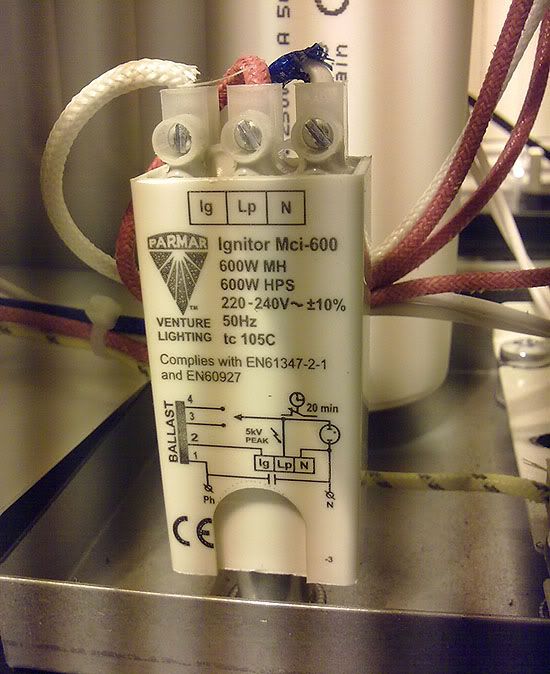
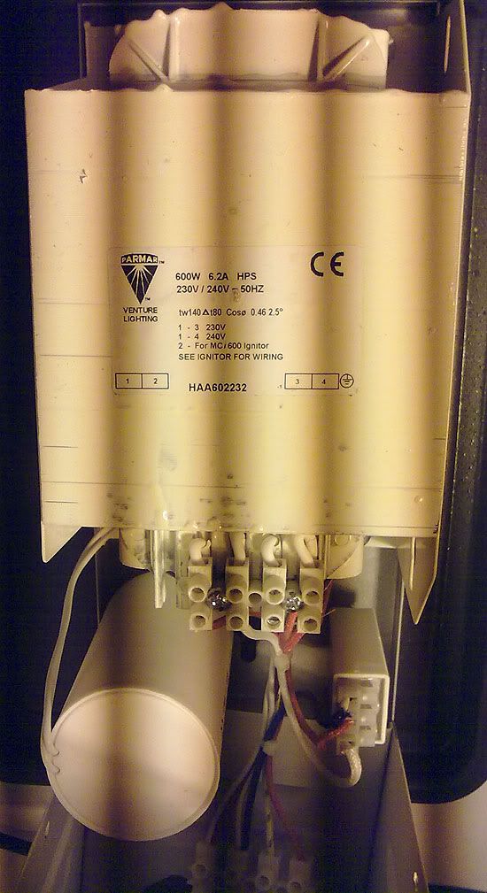
            • Here are some pictures of a UK 600w ballast for metal hallide or high pressure sodium bulbs.


              If you connect one of these bulbs as the load you can loop it as a self runner using a solar panel. This should gain some more interest to the thread and add more minds and more direction.


              Even better use your replication to run one of these:

              CT6850, Impact Wrench, Cordless, 18 Volt, Slide-on Battery, 1/2" Drive (U.S.)

              Then the torque output from the impact wrench could run one of these:

              http://www.alxion.com/produit/500ATK2M.pdf

              Just another way to go and food for thought..... I'm sure it can be done better and cheaper with electronics and coils. At least you can then use as little or as much electric for you house as you want and the generator keeps turning regardless.


              Another thought! In my conversation with Richard from RMCybernetics, he mentioned he can make circuits that with lock into the resonant frequency and adapt depending on the load. I think he also said spark gap can be replaced by using a slave and master frequency.

              He informs me that he has a slot to begin work on custom projects in March.

              Possibly a person to help us overcome some obstacles, although there are some amazing minds coming together here. I'm quite happy for companies to get involved in different aspects of this device. It makes it much harder to suppress.

              Comment


              • Originally posted by Duncan View Post
                I only have a partial mental picture of what you have drawn here Dave please amplify it
                check Dave's thread, he explores the figure he posted:

                http://www.energeticforum.com/renewa...ld-magnet.html

                Signs and symbols rule the world, not words nor laws.” -Confucius.

                Comment


                • Originally posted by mr.clean View Post
                  YES, definitely the problem,

                  Hey, question.. i want to use a relay and this other square gen i made for cap pulsing at 60hz to output,

                  (i know about the resistor/lowing freq and volt divider arrangement)

                  But i want to try it this way, to keep the caps charged rather than dumping all at once everytime.

                  Ive been looking around, but no one is using 600+ volt caps and a relay w/signal gen,

                  how to keep these charged and pulse at 60hz?? any advice?
                  I've been tossing around idea's to discharge a smaller cap that is charged from a bank of caps, making the stored energy many times greater than the load needs.

                  The problem with relays is they have a naturally small gap which doesn't allow for a voltage of very high potential before they simply act as a spark gap. So... why not build a relay that is a spark gap with a variable gap controlled by voltage. Back in the 60's and before, we used mechanical voltage regulators, it would seem a good time to recreate one of these old gizmos for a different purpose...

                  Below is a basic diagram for one... The output cap would be sized for the load you want to run ( such as the J/s needed to drive a load at 60hz ), the solenoid wound to pull the core in and out based on the current flowing ( lots of turns of small wire so your not wasting much energy ), and a spring for adjusting the voltage. When the output cap is full the core is pulled into the solenoid breaking the connection from the bank. The cap is discharged into the load the spring pulls the core out and connects to the bank again and is filled to a voltage set by the spring tension.

                  Since it's voltage controlled you could set the output for just about any voltage you needed - one less conversion. Just one of the many crazy ideas that I've pondered that might have the potential to work....
                  Last edited by dragon; 03-14-2012, 02:52 AM.

                  Comment


                  • wise words

                    Originally posted by Farmhand View Post
                    Yeah they are prone to insulation damage, but I use two, I anti parallel the primaries the two cores are joined and grounded along with one end of each secondary (which are already joined to the core), then there is over 4000 volts between the two HV actives. They can fire a spark gap quite wide and fast with anything from 60 Hz to 360 Hz but at the higher frequencies there is less power because of the frequency induced impedance. I see now my previous problems may have been a faulty series driving cap I replaced them and the original transformers are working fine now. Hmmmff. Cool. The series driving caps I was using were the very same ones I charged to 800 volts so it's no wonder, they are only 275 volt caps they must have been already damaged and faulter when the pressure is on them.

                    I use them about 140 Hz mostly and restrict the current through the primary by using one series capacitor 2.2 uF in the active line of each primary. I drive them with my converter which has two 240 volt out of phase outputs. restricting the primary current is essential with MOT's, with no current restriction the input power goes to over 500 watts at the flick of the switch. With 2.2 uf in one line of the primary the max input is about is about 80 watts per MOT at about 180 Hz. Each cycle the cap will only pass so much current, I can also use smaller ones for less current this would make it possible to connect to the wall or an appropriate inverter. But I do agree an oil filled "pig" would be nice to make, I have some transformer oil maybe I should boil some out and put a pair of MOTs in oil and crank them up to see what they can take.

                    To FRC, if the halide transformer has a 110 or 240 volt primary input you will need an appropriate AC source to drive them, I'm using a 12 to 240 volt home wound converter, the secondaries of my converter are very close to the 200 mH or so of the MOT's which is why it works well for me I think. I'm picking the fruits of a lot of difficult and time consuming work it took to build and wind the converter, I'm very happy with how it works though so far. I feel as though I could safely power my MOTs from the wall but that's only because of the experiments I've done with the converter slowly bringing the frequency down and power up till I have what I want and can use them at 60 Hz with reasonably low input power. But I still wont do it, I've been electrocuted by 240 from the grid and I know what it feels like, I don't think my body could take it now at my age. I handle the 240 volt outputs at over 20 Khz but when I use 60 hz I don't touch anything while it's turned on. My feeling is that a small commercial 150 watt inverter or something might no take driving a transformer very well but I really don't know, that could be an option.

                    What are the input and output voltages of the halide transformer ?

                    I'll make a drawing of how I use the series capacitor to restrict the primary current.

                    What I find is that driving a coil like a flyback or ignition coil with DC pulses using a transistor the transistor heats up from the transients in the primary but using AC that's not a problem. A two phase inverter circuit has the advantage of switching the primary current back and forth which means when there is no load the flux will build to maximum and the transformer will idle with very little current draw and virtually no heating of the transistors and very few transients. So I use AC to drive the HV transformers then rectify the HV to use HV DC for the primary tank circuit. This way the transistors switching the supply current from the source battery don't overheat even when switching 100 watts. Try switching 100 watts DC one way through a transformer or coil with out removing or suppressing the spikes or active cooling and the transistor probably wont last very long. With less than 1 amp at 12 volts (10 watts) it might be OK but 100 watts might tell a different story.

                    Remember when there is a chance of a shock keep your left hand in your pocket.

                    Cheers
                    That is great info, wow. So youre saying drive it with ac and dc out of the hv diodes, nice. Just like dons
                    Because i HATE cooling transistors, i have added a fan not long ago lol
                    Recently also tried 24 volts as rmcybernetics had shown, but just series the bats, not switched. And works EVEN better, and can lower the current respectively w/duty cycle.

                    Any idea how i could use a relay with these +600v charged 30uf's, driven by sig gen at 60hz?
                    In the beginner's mind, there are many possibilities.
                    In the expert's mind there are few.
                    -Shunryu Suzuki

                    Comment


                    • LC Tank

                      Originally posted by Duncan View Post
                      Whilst I'M not hyping this company in particular ,, I would seriously think of working along the same lines lines (or some thing similar) / Its relatively cheap and its the foundation of Mr Cleans circuit . ( which you’ve seen working) As you will see It has the advantage of a variable frequency HT power supply this company sticks you £50 for the unit but the schematics there and a 555 will cost buttons .. with a variable frequency supply you can tune anything to anything (within reason) couple of coils from the scrap yard .. It makes sense XL is directly proportional to frequency and XC is indirectly proportional to frequency so get some where near and then hit the nail right on the head by altering the frequency slightly.. takes a lot of the hassle away
                      RMCybernetics - DIY Mini Tesla Coil
                      LC tanks are on secondary coils; primary can be done without caps this I read it in one of Zilano texts if I'm not wrong.

                      Comment


                      • Originally posted by dragon View Post
                        I've been tossing around idea's to discharge a smaller cap that is charged from a bank of caps, making the stored energy many times greater than the load needs.

                        The problem with relays is they have a naturally small gap which doesn't allow for a voltage of very high potential before they simply act as a spark gap. So... why not build a relay that is a spark gap with a variable gap controlled by voltage. Back in the 60's and before, we used mechanical voltage regulators, it would seem a good time to recreate one of these old gizmos for a different purpose...

                        Below is a basic diagram for one... The output cap would be sized for the load you want to run ( such as the J/s needed to drive a load at 60hz ), the solenoid wound to pull the core in and out based on the current flowing ( lots of turns of small wire so your not wasting much energy ), and a spring for adjusting the voltage. When the output cap is full the core is pulled into the solenoid breaking the connection from the bank. The cap is discharged into the load the spring pulls the core out and connects to the bank again and is filled to a voltage set by the spring tension.

                        Since it's voltage controlled you could set the output for just about any voltage you needed - one less conversion. Just one of the many crazy ideas that I've pondered that might have the potential to work....
                        Thankyou very much ! Good stuff
                        In the beginner's mind, there are many possibilities.
                        In the expert's mind there are few.
                        -Shunryu Suzuki

                        Comment


                        • Originally posted by Guruji View Post
                          LC tanks are on secondary coils; primary can be done without caps this I read it in one of Zilano texts if I'm not wrong.
                          you are going to use this "Tesla coil" backwards as Mr Clean has indicated so primary and secondary are sort of arbitary terms, but all the resonance particulrs still apply, and so Hertzian resonance between HT power supply and the many turn coil and Linear wave (out of phase 1/4 wave) resonance with coil which has fewer turns. ZZZZs work I love to bits there are circuits there I have seen nowhere else and prints out of books I cant track down. I'm certain great stuff will issue but at the moment I can't understand enough to make a single circuit work, I have never seen one work, I dont have the nouse to advise.I would be inclined to follow the machine you have seen working with the directions and circuit given by Mr C which is in turn based loosley on this Tesla coil RMCybernetics - DIY Mini Tesla Coil And driver circuit
                          Whatever you can do,or dream you can,begin it.Boldness has genius,power and magic in it.Begin it now.

                          Comment


                          • Thanks soundiceuk

                            Thanks soundiceuk for the info and the pictures and links. I am using two small solar panels right now to charge 12v batteries with the halyde. I am getting
                            heat, light, and electricity. With enough solar panels and batteries I think one
                            could acheive OU or close to it. With enough batteries and an inverter to power
                            the light I am sure this could be achieved. Good to see someone else thinking
                            along the same lines I am.

                            George

                            Comment


                            • Originally posted by Duncan View Post
                              you are going to use this "Tesla coil" backwards as Mr Clean has indicated so primary and secondary are sort of arbitary terms, but all the resonance particulrs still apply, and so Hertzian resonance between HT power supply and the many turn coil and Linear wave (out of phase 1/4 wave) resonance with coil which has fewer turns. ZZZZs work I love to bits there are circuits there I have seen nowhere else and prints out of books I cant track down. I'm certain great stuff will issue but at the moment I can't understand enough to make a single circuit work, I have never seen one work, I dont have the nouse to advise.I would be inclined to follow the machine you have seen working with the directions and circuit given by Mr C which is in turn based loosley on this Tesla coil RMCybernetics - DIY Mini Tesla Coil And driver circuit
                              One way to assure both L1 tank and L2 secondary is resonant with each other is to find the values of the primary tank and reverse them for the secondary, or visa versa using the secondary values to build a primary.

                              For instance if you have a 15uh inductor and a 5000pf cap as the primary it will be resonant at 581khz. If you make the secondary coil with a 5000uh inductor with a total capacitance of 15 pf (interwinding and top load ) it will also be resonant at 581khz ( 581,151.68 hz to be precise ).

                              Simply reverse the values and you have a 2 coil resonant structure.

                              Comment


                              • Originally posted by mr.clean View Post
                                That is great info, wow. So youre saying drive it with ac and dc out of the hv diodes, nice. Just like dons
                                Because i HATE cooling transistors, i have added a fan not long ago lol
                                Recently also tried 24 volts as rmcybernetics had shown, but just series the bats, not switched. And works EVEN better, and can lower the current respectively w/duty cycle.

                                Any idea how i could use a relay with these +600v charged 30uf's, driven by sig gen at 60hz?
                                If using DC is working for you keep doing it, if the object is low input and
                                there is no overheating then it's all good. If it works for you is the main thing.

                                I've been thinking about the relay idea but so far I'm skint for idea's on that.
                                I'm thinking a relay might fuse up. 600 volts is a difficult range to deal with.

                                I'm using this supply for Tesla coils and stuff, I want to be able to put 10 or
                                20 amps through the 12 volt switches which they should take no probs they
                                are rated to 30 amps each. 10 seems no probs since I doubled the wire in and
                                out of the fets on the board and the voltage drop reduced too. I should
                                measure the resistance of the entire current paths.

                                Cheers

                                Comment

                                Working...
                                X