 Tweet
Tweet
Zilano
Farmhand: I agree with you re Zilano's wrong use of terms. But remember experts very rarely create anything - Mavericks do. So Mavericks explain things according to their own understanding.
This is always one of the problems facing clasically trained physicists - they have to understand everything on their terms. If someone uses laymen's terms to try and convey a meaning it's very easy for a trained individual to pounce on semantic errors.
That's why I constantly refer to Tesla/Zilano/Don Smith/Kapanadze similarities. That way we can discern the truth regardless of wrong terminology used.
Whatever we may think of Don Smith or Zilano it is certain that Kapanadze did it.(And of course Tesla).
So we can agree the following
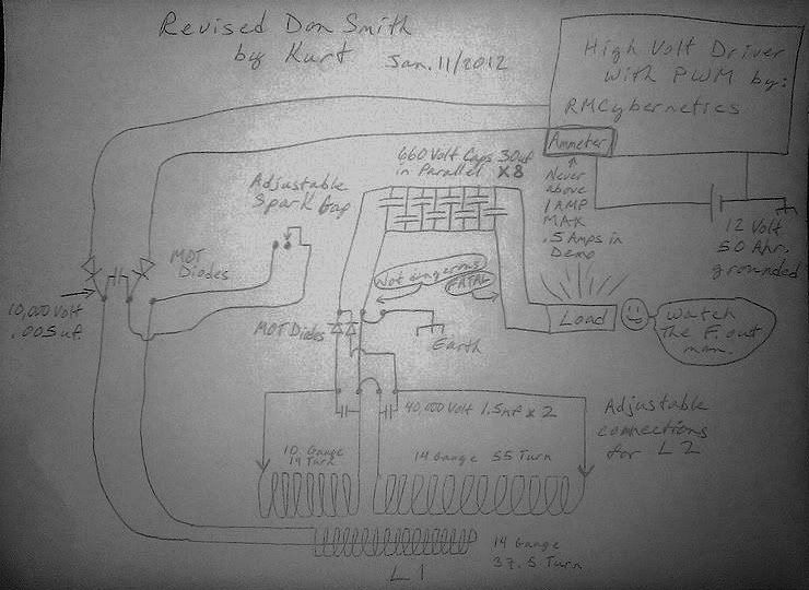
1 spark gap is important
2 L1 to L2 ratio has to be quarter wave or multiple of same - subject to Tesla's variations.
3 L1 to L2 coupling has to be loose
4 Ground wire affects wavelength if coupled direct and not blinded by a capacitor.
5 OU exists
6 L1 to L2 coupling is a radio coupling as well as inductive.
7 Resonance is vital. No resonance - No OU.
8 Resonant output transformer is vital
9 Zilano has given us answers to some of Don Smith's intentionally omitted secrets. ie resonant output transformer and possible use of ferite.
Farmhand: I agree with you re Zilano's wrong use of terms. But remember experts very rarely create anything - Mavericks do. So Mavericks explain things according to their own understanding.
This is always one of the problems facing clasically trained physicists - they have to understand everything on their terms. If someone uses laymen's terms to try and convey a meaning it's very easy for a trained individual to pounce on semantic errors.
That's why I constantly refer to Tesla/Zilano/Don Smith/Kapanadze similarities. That way we can discern the truth regardless of wrong terminology used.
Whatever we may think of Don Smith or Zilano it is certain that Kapanadze did it.(And of course Tesla).
So we can agree the following
1 spark gap is important
2 L1 to L2 ratio has to be quarter wave or multiple of same - subject to Tesla's variations.
3 L1 to L2 coupling has to be loose
4 Ground wire affects wavelength if coupled direct and not blinded by a capacitor.
5 OU exists
6 L1 to L2 coupling is a radio coupling as well as inductive.
7 Resonance is vital. No resonance - No OU.
8 Resonant output transformer is vital
9 Zilano has given us answers to some of Don Smith's intentionally omitted secrets. ie resonant output transformer and possible use of ferite.


Comment