Announcement

Collapse
No announcement yet.

Donald Smith Devices too good to be true

Collapse
X
 
  • Filter
  • Time
  • Show
Clear All
new posts

  • Thanks! zilano! Can anybody read Russian? I'll try it at our secretary. She claims to have learned Russion while living in the former German "democratic" Republic. But she has no technical knowledge at all. Perhaps she can transfer it in normal text in order to crank it through google translator.

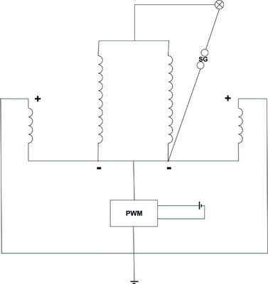
    My personal notion regarding schematic function (comments welcome):

    A: Middle bottom of schematic
    1. Transformer (Tp3) from obviously 50 Hz 220V to some lower voltage DC. Let's suppose somewhere between 12V and 24V.
    2. Switch for start / stop in the DC power line

    B: Left hand side
    1. Higher frequency oscillator Meissner type (corresponds to JT)
    2. Transistors work push/pull towards an artificial middle voltage C3/C4. This saves additional 2 Transistors in order to build a true H-Bridge. (BTW: Stepper motor drivers use cheap H-Bridges up to 40V/ 3.5 A i.e. TB6560AHQ)
    3. Meissner transformer 40/40 turns (Tp1) (Air core? / Ferrite?)

    C: Middle of schematic (bridge betwen transformer Tp1 and Tp2 and Tp3)
    1. On same core from above core: harvest coil with middle connector. 120 turn (1x 120 or 2x120?) (cw/ccw?)
    2. Connected to harvest coils there is a normal 220V/50Hz transformer for low voltage (see A
    3. Transformer connected via 2 capcitors c5 c6
    4. Power output after C5/C6 with 220 V switch
    5. Output with earth connection (safety or essential?)

    Discussion:
    This normally should be a high frequency output. Don Smith prefers his (for me) not understandbale "frequency scale down" resistor. Russians seem to prefer a more understandbale version. They modulate the high frequency by another 50 Hz transformer (Tp3). I'm not completely clear about this. Comments welcome!

    D: Right hand side
    1. Another Oscillator of Meissner type. (50Hz?) adjustable
    2. Transformer Tp3 / Transformer with (Iron core?)
    3. Output coils with spark gap (seems to modulate high frequency)
    4. Earth connection. (individual or same as 220V output? / safety?/functional?/ essential?)


    Discussion: Not celar how this modulation works along with this spark gap.

    @Zilano: I understand your words regarding cold and hot. But my heart is not open to understand. I need to learn alot! And I understand that knowledge needs more than one way in order to be received.
    rgds John
    Last edited by JohnStone; 12-20-2011, 07:03 PM.
    Experts spend hours a day in order to question their doing while others stopped thinking feeling they were professionals.

    Comment


    • Originally posted by zilano
      modify. u have nst which has dual ac outputs. we need pulsed dc before spark gap and a diode after spark gap.

      Hello Zilano and everybody!

      I really do not understand, here is a short circuit. My flayback is having
      only one secondary.
      I monitor the topic for the last six months, and I decided to try the device as a hobby.
      Is it possible to get some guidance. However, It looks only two people on the forum actually build the device!!
      Too bad. I did insert 1 more diode before spark gap and my littli 220v signal light is having a 1/4 of light, with just one cable connected. I can't do any measurement because i'm still waiting for hv probe.

      have a nice night

      Zinano thanks anyway.

      Comment


      • Originally posted by zilano
        modify. u have nst which has dual ac outputs. we need pulsed dc before spark gap and a diode after spark gap.
        Hi zilano:

        Thx for your reply. But some trouble yet. Sadly, i have no real earth ground connection on 10th floor. So i modify the circut like this:


        I think it's pulsed dc before spark gap, but light does not work.

        BTW: The diods are HVM12 350 type (12kv, 350ma).
        Last edited by ostone; 01-18-2012, 08:14 AM.

        Comment


        • Originally posted by JohnStone View Post
          High nightwind,
          that's exact my present concern. Some thoughts regarding:

          Such a spark circuit could be built as module to check different coil setups under controlled conditions. This is an important factor for any electrical OU setup.

          Just some thoughts not being ripe for digesting. I am shure there are a lot of more valuable facettes out there to look for - being absent in my mind.
          rgds John
          @bbem

          It looks exactly same. Zilano jst copy picture, hehe.... Now I can see, that triggering on diode is not
          triggering on diode, but device is thyristor, and whole setup is now 'semielectronic spark gap' which I
          was thinking about long time ago... More details below. Thanx for the link.

          @John Stone

          regarding 'kick' into system. Last time we agreed, that radiant energy is released during sharp pulse with high voltage gradient.
          To keep system resonating, yes, those kicks must be synchronized with waveform and I don't thing is really necessary to
          shoot pulse in dead point. For testing purposes is much more convenient to sense 'zero' crossing of secondary wave and do proper
          phase shift to shoot another pulse.... See picture. Pulse is fired every cycle only once. This can be hardly done with
          spark gap itself. More accurate timing is necessary and best it jst to synchronize firing pulses with secondary
          momentum, so you get self adjusted resonant circuit, which is the best. If any 'parameter' (L/C) in system will change, driver
          via feedback will follow to keep resonance.Thus controllable sparg gap must be employed. Now I can see, that you've come up
          with same ideas, nice !

          Digital approach: DSP approach or any microprocessor solution is not a problem. I was working on that concept past few days and
          have pretty clear picture. This solution is the best, as you can adjust all parameters and do very precise timing to keep resonance
          at any cost.

          Analog approach: is good too, three comparators, one set/reset circuit and one AND gate will do the job. Idea is to
          sense zero crossing, recognize 'direction' of wave and fire pulse when comparators match. Easy. only concern is feedback sensing
          coil and its signal conditioning. To use it with comparators you need bias input and then process it.
          One comparator will sense zero crossing, one will sense voltage of stepping wave (firing pulse width), and last one direction of wave.
          Set/reset will do blocking in negative quadrants and AND will put fire / blocking together.

          To get precise timing, spark gap must be controlled with trigger. There are two options. To use spark gap with shield (like xenon flash)
          to fire -HV pulse to allow spark jump or jst implement HV IGBT to trigger HV to spark gap. After voltage will be present on electrodes,
          spark will fire.... Solution is easy. Just to assemble it and test. There will be some transition delays, so phase shift possibility
          is crucial to tune whole system.

          I am still thinking about damn spark gap... Its very unreliable component in whole system. If only HV pulse is necessary to trigger
          radiant event (as per discussion before), then HV MOSFET will do the job. I can test 4kV silicon device to fire pulse on exact duty
          cycle and period of course, to the primary coil, but question is.... if spark gap is giving some extra energy to the system or not....

          Zelina said spark gap is the best, but I still don't like that... Why is best ? Because of easy HV handling ? Because of 'magic of the
          spark' ? Who knows.

          I will develop firing circuit to test it. With auto resonance adjustment (based on damped circuit oscillations) and external
          phase / duty cycle control. Duty cycle on spark gap can't be hardly done, but frequency yes... Because of time issues, will do
          it in January.

          Coil setup: Please put together coil setup. There is plenty possibilities, but open circuit must be done ? Fancy setups with Cu tube
          and ferrite cores are not gud at the moment, as we need concept proof and single layer air cores are easy to wind. See Don's designs.
          I would stick with Tesla based circuits for first design ? Any serious suggestions to proceed with ?


          regards

          Cinan
          Attached Files

          Comment


          • selfonlypath

            @Cinan
            A digital approach for getting OU:
            selfonlypath's Channel - YouTube
            Very interesting/educational videos of this guy called "selfonlypath".
            Keep up the good work!

            @Hope
            He is using a 'diode plug' to harvest.
            TransVerter / Part 5 - YouTube

            ps. Pay attention at what he is saying after 8min on this Transverter video.
            Last edited by bbem; 12-21-2011, 12:08 PM.

            Comment


            • Thanx for link. I have similar approach, but much much easier to implement. Air core is best to work with and I will focus on that.

              Comment


              • Originally posted by editor View Post
                Hello Zilano and everybody!

                I really do not understand, here is a short circuit. My flayback is having
                only one secondary.
                I monitor the topic for the last six months, and I decided to try the device as a hobby.
                Is it possible to get some guidance. However, It looks only two people on the forum actually build the device!!
                Too bad. I did insert 1 more diode before spark gap and my littli 220v signal light is having a 1/4 of light, with just one cable connected. I can't do any measurement because i'm still waiting for hv probe.

                have a nice night

                Zinano thanks anyway.
                I am sure are here more guys that tried to make this device but they didn,t posted their results...
                I tried this circuit too using home made flyback with just one secondary .I don,t think is important to have 2 secondaries .Anyway the circuit was an failure .I was disappointed; maybe I will give it a try again in another day...

                Comment


                • Hi guys, here is my input.

                  Last night after watching some more Don Smith videos I decided to connect a wire from the earth of the plug socket to my ignition coil positive.

                  I haven't got a clue why I decided to do this, but I'm very glad I did.

                  All of a sudden the HV return after the xenon flash tube sent a constant spark 1 & 1/2 inches of bright blue light to the negative terminal of the ignition coil when placed nearby.

                  If the spark is that big, how many volts would it be?

                  When the earth is taken away it only does 2-3mm.

                  What exactly is happening here? Am I tapping the earths energy and feeding it into the circuit?

                  I haven't had any chance to experiment since as I woke my missus up whilst doing so. Whoops!

                  The fact the spark is that long scared the sh@t out of me, although the shocks from high frequency HV only sting a little. This sort of voltage increase needs to be investigated and I don't fancy copping a shock from that.

                  It can probably be done on any of the joule thief etc coils too I guess.

                  Comment


                  • @Soundiceuk
                    Sounds great, could you give a small drawing of your setup?

                    I guess the problem we often have is the fact that we think to much in closed/'old fashion' electric circuit style.

                    Comment


                    • Earth Ground

                      Originally posted by ostone View Post
                      Hi zilano:

                      Thx for your reply. But some trouble yet. Sadly, i have no real earth ground connection on 10th floor. So i modify the circut like this:


                      I think it's pulsed dc before spark gap, but light does not work.

                      BTW: The diods are HVM12 350 type (12kv, 350ma).
                      You can substitute the NEGATIVE terminal of a car battery (lead-acid accumulator) for an earth ground(TESLA).
                      Or a central heating radiator. But be careful, if you get a short, other people touching the unpainted surface can get a shock.
                      You can also substitute a big bowl of water. The general purpose of a ground is to set up a STANDING wave (AC) between the device and ground.

                      Comment


                      • Earth Ground 2

                        I forgot: You can also use a mains plug with just the earth connected. That will work OK in most cases. Be careful re-wiring a mains plug. If you get it wrong you could DIE! The good news is that you don't have to have the mains switch on - the ground should be attached even if power is off - if the electrician has done a correct job. In any case you should work with a contact breaker - just in case. Be safe, be careful - don't do it unless you are 100% sure.

                        Comment


                        • Originally posted by a.king21 View Post
                          You can substitute the NEGATIVE terminal of a car battery (lead-acid accumulator) for an earth ground(TESLA).
                          Or a central heating radiator. But be careful, if you get a short, other people touching the unpainted surface can get a shock.
                          You can also substitute a big bowl of water. The general purpose of a ground is to set up a STANDING wave (AC) between the device and ground.
                          a.king21, thx for your explanation.

                          But the light is not work also.

                          Comment


                          • Originally posted by bbem View Post
                            @Soundiceuk
                            Sounds great, could you give a small drawing of your setup?

                            I guess the problem we often have is the fact that we think to much in closed/'old fashion' electric circuit style.
                            Certainly.... I was using two igntion coils at the time.


                            Here is the driver:

                            Last edited by soundiceuk; 12-22-2011, 10:29 AM.

                            Comment


                            • I think it's about 30000 volts to jump one inch through air between two sharp points. High power ignition coils can easily do more than that. Be safe.
                              There is no important work, there are only a series of moments to demonstrate your mastery and impeccability. Quote from Almine

                              Comment


                              • Originally posted by ostone View Post
                                Hi zilano:

                                Thx for your reply. But some trouble yet. Sadly, i have no real earth ground connection on 10th floor. So i modify the circut like this:


                                I think it's pulsed dc before spark gap, but light does not work.

                                BTW: The diods are HVM12 350 type (12kv, 350ma).

                                Hi zilano, correct me please.


                                Thanksssssssssssssssssssssssssssssssssssssssssssss ssssssss!
                                Last edited by ostone; 12-22-2011, 06:39 PM.

                                Comment

                                Working...
                                X