Announcement

Collapse
No announcement yet.

Donald Smith Devices too good to be true

Collapse
X
 
  • Filter
  • Time
  • Show
Clear All
new posts

  • :-)

    Originally posted by TEKTRON View Post
    Jaharmon, That bucket setup of yours is about as far away from a ground as you can get

    Use mains ground or drive an 8 foot proper copper plated ground rod into the ground outside.
    Ahhh... Thanks. I kept asking about grounding before, but nobody really spoke up. I'll be sure to continue doing stupid stuff. ;-)

    Many thanks Tektron.

    Comment


    • Originally posted by jharmon View Post
      Ahhh... Thanks. I kept asking about grounding before, but nobody really spoke up. I'll be sure to continue doing stupid stuff. ;-)

      Many thanks Tektron.
      LOL no problem me too

      Comment


      • Ground=magnetic current

        The best ground you can have is copper or BRASS rod, not steel.
        Steel will short circuit magnetic current instead of allowing it to flow.

        HTML Code:
        However, when stating the wire then GOES TO GROUND, we need to expand on just WHAT TYPE of ground. We DO NOT use a standard electrical ground rod that is copper-coated steel. The ground rod should be the same thickness and distance into the ground as an electrical ground rod BUT it should be made of a copper/brass metal combination. Magnetic current tends to GRAB the steel part of the electrical rod that then STOPS THE FLOW causing what could be called a magnetic short circuit. 
        Free energy magnetic water purifier using zero point energy and cold fusion

        Comment


        • Small circuit for consideration from Don Smith explanations
          Attached Files

          Comment


          • Originally posted by Guntis View Post
            mmm, No coment.... Working device and selfruning Device, maybee have diferent meanings
            I do understand that principles of Zilano is ‘’resonance in coils’’ and your principles is some think like the picture in my attach show.
            If in this Kodak circuit we attach a 50Hz coil for modulation and a coil for load arranged at 90 or 180 degrees and if we arrange all that as Mislavskij’s transformer, we will have an working device like SR or Kapanadze?
            Attached Files

            Comment


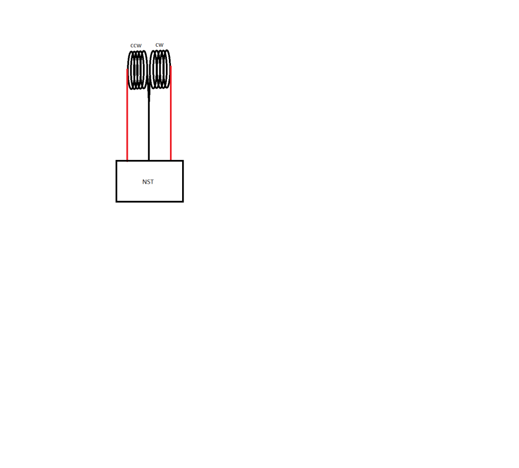
            • The primary is the problem, it needs to be wound like this
              Half of the Answer is knowing the right Question

              Comment


              • Originally posted by Felix_the_cat View Post
                The best ground you can have is copper or BRASS rod, not steel.
                Steel will short circuit magnetic current instead of allowing it to flow.

                HTML Code:
                However, when stating the wire then GOES TO GROUND, we need to expand on just WHAT TYPE of ground. We DO NOT use a standard electrical ground rod that is copper-coated steel. The ground rod should be the same thickness and distance into the ground as an electrical ground rod BUT it should be made of a copper/brass metal combination. Magnetic current tends to GRAB the steel part of the electrical rod that then STOPS THE FLOW causing what could be called a magnetic short circuit. 
                Free energy magnetic water purifier using zero point energy and cold fusion

                Thank you Felix, I did not know that

                Comment


                • Hi,

                  Is it save to use variable vacuum capacitors for primary or/and secondary coil?
                  Omnicor: Vacuum capacitors
                  http://www.omnicor.com/docs/Var%20Va...on%20Guide.pdf
                  Google: Variable vacuum capacitors

                  Could be handy to tune on resonance, but pretty Expensive.
                  Reading the specs: caps can be used at Mhz HV and high Arms @picoF!

                  Also I found a similar coil arrangement known as a LCT "Link Coupled Tuner" that uses variable vacuum capacitors and center tapped L2 coil. L1 is called Link coil.

                  Best Regards
                  Last edited by cognito; 11-15-2011, 01:14 PM.

                  Comment


                  • about the formulas

                    Hi all, i'm a newer here.Very interesting.

                    P = 0.5 x C x (V squared) x (HZ squared)
                    So, here P is which power(measure the out coil L2?), C is which capacitor(the L1 matching capacitor?), V is which voltage(between L1?), and HZ is which frequency?
                    the force frequency or the resonance frequency?

                    and follow formula?
                    P = 0.5 x C x (V squared) x HZ
                    P = 0.5 x L x (I squared) x HZ

                    could any one help me?
                    Last edited by ostone; 11-15-2011, 03:45 PM.

                    Comment


                    • Originally posted by zilano
                      one can study the coils and resonance without using high voltage coz with the dangers involved with high voltage.

                      one can use dc motors 12 v as pulsed dc supply and can study various coils like singular coils or bifilar coils or caduceus coils and even don arrangement.

                      HERE CAPS ARE 0.01 MICROFARAD 200-300 VOLT DISC TYPE AC. WIRE GAUGE CAN BE VARIED FROM 22 AWG TO 28 AWG

                      THIS IS NON INDUCTIVE CIRCUIT SO NO DIODE IS USED IN SERIES. FOR INDUCTIVE CIRCUIT A DIODE HAS TO BE USED TO SAFEGUARD INDUCTIVE KICKBACK


                      RGDS
                      ZZZZ
                      zzz,thanks! I will try and learn. Keep post.

                      Comment


                      • Originally posted by zilano
                        one can study the coils and resonance without using high voltage coz with the dangers involved with high voltage.

                        one can use dc motors 12 v as pulsed dc supply and can study various coils like singular coils or bifilar coils or caduceus coils and even don arrangement.

                        HERE CAPS ARE 0.01 MICROFARAD 200-300 VOLT DISC TYPE AC. WIRE GAUGE CAN BE VARIED FROM 22 AWG TO 28 AWG

                        THIS IS NON INDUCTIVE CIRCUIT SO NO DIODE IS USED IN SERIES. FOR INDUCTIVE CIRCUIT A DIODE HAS TO BE USED TO SAFEGUARD INDUCTIVE KICKBACK


                        RGDS
                        ZZZZ
                        Thanks Z for these hints!
                        Starting with lower Voltage ist exactly what i do. I play around with spark arrestor 250 or 350 V and capacitors below 2000V - easily available, handy and cheap. Very healthy for scope and other equipment and user as well :-)
                        No distinct success yet. I just started to learn hands on.
                        Regards
                        John
                        Last edited by JohnStone; 11-16-2011, 09:52 AM.
                        Experts spend hours a day in order to question their doing while others stopped thinking feeling they were professionals.

                        Comment


                        • Hi all,
                          experimenters being short of funds who search for a drawing tool for schamatics. I use Kicad. It is free and fully open source and handy as well. Very easy to start if standard components employed. Drawback: Mouse actions not consequent WIN conform but learnable.
                          Multilayer layout capability included if required.
                          "KiCad is an open source software suite for electronic design automation (EDA). It facilitates the design of schematics for electronic circuits and their conversion to PCBs (printed circuit board) design. KiCad was developed by Jean-Pierre Charras, and features an integrated environment for schematic capture and PCB layout design. Tools exist within the package to create a bill of materials, artwork and Gerber files, and 3D views of the PCB and its components."

                          It may help to post your schematics in this thread in a clear drawing and help your own lab documentation. I recommend to add a version note in every schematic for clear reference.
                          Regards John

                          PS: I do not intend to start a Kicad or other tool discussion in this thread - the internet has plenty of them. It is just a hint.
                          Last edited by JohnStone; 11-16-2011, 10:07 AM.
                          Experts spend hours a day in order to question their doing while others stopped thinking feeling they were professionals.

                          Comment


                          • Thinking...

                            Originally posted by zilano
                            the gfi sees no load so its tripping in don case.
                            Have to think about your other tips, but "light bulb" went on for this one.

                            Was thinking GFI circuit in NPS was looking for equal current in as out. But not quite.

                            A tube of neon has total voltage drop until the signal hits the breakdown voltage for the tube. Then, current flows and voltage drop goes to zero... like a spark gap.

                            So the NPS probably expects no current and high voltage drop across the leads at the beginning of each cycle.

                            Hmm. Anytime you have an untuned cap / coil combination across either of the leads (with neon or spark gap in series), the NPS will either push or pull current on one of the leads right away... this will look like a ground fault.

                            ok. I guess i can at least find the freq of the NPS by firing across a spark gap by itself.

                            Comment


                            • Originally posted by zilano
                              Hi john!

                              this paragraph contains important info that all people r looking for ou.

                              the simplicity lies in two caps across coil so that one is in series with coil and the other in parallel. the cap that is paralllel must be of high capacity and the one in series must be low capacity that it passes hf of the coil to the cap in parallel. the coil is simple coil and ferrite can be used as well as air core. the above combination forms an open circuit. this is basic primary coil. for secondary u can use simple coil also. the primary coil with two cap combination is pulsed with hv dc. one can use avramenko for low input or a direct nst can be used. but the pulse must be hvdc. one can use mov 120 volt or 230 volt or 250 volt as the secondary coil output is hvac and have to be lowered in voltage, rectified and pulsed either using vibrator type combination or igbt.


                              regards

                              zzzz
                              Hi Zilano,
                              sorry - can't imagine what schematic you refer to. Especially the cap in series and parallel. You are so far advanced! Some additional hints available?
                              Thanks for sharing!
                              Regards
                              John
                              Last edited by JohnStone; 11-16-2011, 06:40 PM.
                              Experts spend hours a day in order to question their doing while others stopped thinking feeling they were professionals.

                              Comment


                              • How much HVDC

                                @ Zilano

                                Your saying "...the pulse must be HVDC." how much should that be 1000v-2000v or what is the minimum voltage required.
                                And at what duty cycle 10%-50%-80%.

                                Thank you for all your insights,much appreciated.

                                Comment

                                Working...
                                X