Announcement

Collapse
No announcement yet.

Donald Smith Devices too good to be true

Collapse
X
 
  • Filter
  • Time
  • Show
Clear All
new posts

  • post 1283 page 43

    Originally posted by Guruji View Post
    Regarding Don circuit if flyback is used? with a driver circuit or by an inverter?
    Thanks.
    Hi Guruji,
    I use a ZVS driver and it works well. the mosfets don't get warm and the output is a sinewave.
    This is the link.
    Teravolt.org - ZVS Driver
    You can vary the capacitor of .68UF and the turns on your FB to achieve the frequency you want. And if you also want to vary the output voltage you can vary the 12V input voltage by means of a BUZ11 mosfet which is setup as a variable resistor. In this case you should not forget to put a 1N4007 diode across the driver circuit to protect the mosfet against the high bemf voltage in the usual manner.
    The driver circuit is then connected to the source of the BUZ11. The 12 Volt to the Drain and the gate to slider of a potentiometer of about 100k Ohms. The other ends of the potentiometer the +12V and th 0V.
    regards
    FEhunter

    Comment


    • Originally posted by FEhunter View Post
      Hi Guruji,
      I use a ZVS driver and it works well. the mosfets don't get warm and the output is a sinewave.
      This is the link.
      Teravolt.org - ZVS Driver
      You can vary the capacitor of .68UF and the turns on your FB to achieve the frequency you want. And if you also want to vary the output voltage you can vary the 12V input voltage by means of a BUZ11 mosfet which is setup as a variable resistor. In this case you should not forget to put a 1N4007 diode across the driver circuit to protect the mosfet against the high bemf voltage in the usual manner.
      The driver circuit is then connected to the source of the BUZ11. The 12 Volt to the Drain and the gate to slider of a potentiometer of about 100k Ohms. The other ends of the potentiometer the +12V and th 0V.
      regards
      FEhunter
      Regarding BEMF - you should use or let it run free not fight by shorting with diode.
      If you have two legs with secondary coils, one of it should be resonant Lc circuit with frequency matching resonance of the coil core.

      Comment


      • Driver circuit

        Originally posted by FEhunter View Post
        Hi Guruji,
        I use a ZVS driver and it works well. the mosfets don't get warm and the output is a sinewave.
        This is the link.
        Teravolt.org - ZVS Driver
        You can vary the capacitor of .68UF and the turns on your FB to achieve the frequency you want. And if you also want to vary the output voltage you can vary the 12V input voltage by means of a BUZ11 mosfet which is setup as a variable resistor. In this case you should not forget to put a 1N4007 diode across the driver circuit to protect the mosfet against the high bemf voltage in the usual manner.
        The driver circuit is then connected to the source of the BUZ11. The 12 Volt to the Drain and the gate to slider of a potentiometer of about 100k Ohms. The other ends of the potentiometer the +12V and th 0V.
        regards
        FEhunter

        Thanks Fehunter and T1000 I will try this circuit. On the vid it gives a very good spark.
        Thanks

        Comment


        • High Frequency Low voltage device with Spark Gap and Inverter

          Thank you Farmhand.

          Could anybody comment on this please: I have built the driver circuit.The one with the 220 ohm and 20 ohm resistor with one transistor and the feedback coil from the flyback. Unfortunately I only get 11 KHz from the set up. I measured the L1 coil on the flyback and calculated the capacitor need to let it function at radio frequencies.I palced it across the input of L1 to flyback.Again, the reading from my meter said 32 KHz then dropped back to 11 Khz in 5 seconds.Adding other capacitors actually resulted in lowering the frequency.What do you think I am doing wrong?

          Consequently I am fixing to build an oscillator that can give me over 1 MHz. Any suggestions ? 555 chips seem to be have a max of 300KHz. Colpitts seem to be a good choice as well as the two transistor Astable Multivibrator.

          Any advice links hints etc are welcome.

          While I would love to replicate Zilanos Machine I am still aiming at a scaled down version with low voltage,high frequency resonant receivers attached to an inverter with one those under 100 volt spark gap.

          I figured that if I can transmit 12 to 16 volts efficiently at High Frequency (in the MHz range) to a set of resonant receivers hooked up to lest say: 3 inverters around the transmitter, then I should be able to get energy without loading the transmitter just like Don said.That way I could create a feedback loop from one or all the inverters back to the cap or battery at the transmitter.

          In theory it should work as waves from a central source can be tapped at points around the transmitter without interference.Already I see where electric cars have been charged wirelessly with up to 3kW been transmitted wirelessly.

          I could still include a flyback as a spark only but pulsing at the same frequency to disturb the ambient and capture the extra electrons.

          Zilano's Device 1.0
          The next idea I am exploring is to just step down the voltage from a flyback to the 2500 to 4500 range.Then adding caps and continue the circuit ala Zilano.That way I could avoid building a flyback from scratch.What do you think?

          Comment


          • Another FLB circuit

            Hi FEhunter,

            i will build another FLB driver circuit, there are plenty to find on the web.
            Yours look fine, but i want to drive mine with my function generator to be more flexible.

            I am sceptical about any Don Smith device as they seem to be "too good to be true" like this thread says :-)
            Also nobody seems to be able to replicate and give convincing evidence.
            Even Drak has stopped!

            It is impossible with a low resistance coil in a parallel LC circuit to have the (parallel) sparkgap fire.
            The impedance is simply to low.

            So the options are a series LC circuit with the same components (LC) in series and the sparkgap parallel over that
            or keep the parallel LC and put the sparkgap in series.

            I can not picture what you want to do with a car ignition coil as a secondary.
            If you drive it with your FLB, the output voltage would be gigantic!
            Or perhaps you mean to use the secondary of an ignition coil as primary!?

            Anyway, give it a try, and let us know.

            Regards Itsu.

            Comment


            • New page

              There is a new page at FreeEnergyInventions.com about Tariel Kapanadze. It also has stuff pertinent to Smith and Tesla.

              Freeenergyinventions

              Dude, you're curving my space-time.

              Comment


              • Great Thread

                Hi all.
                This is a great thread. I was hoping by the time I got to the end someone would have it all figured out.
                I've been looking at the Don Smith devices and the stuff you're doing here. I think there's something out there and some of you are close if not there. Since the parts aren't real expensive, I'm going to give it a try.

                Comment


                • Originally posted by deggers View Post
                  There is a new page at FreeEnergyInventions.com about Tariel Kapanadze. It also has stuff pertinent to Smith and Tesla.

                  Freeenergyinventions

                  Just so you know... This web site is a known malicious web site, their phishing for identities. Be careful.

                  Comment


                  • Originally posted by dragon View Post
                    Just so you know... This web site is a known malicious web site, their phishing for identities. Be careful.
                    Bugs3 is a free hosting site that has been used in the past by phishers faking the Paypal website. I believe this is why it has gotten a bad rap.


                    Regards,
                    Duane
                    Dude, you're curving my space-time.

                    Comment


                    • Excellent info !
                      Freeenergyinventions

                      Comment


                      • FBT driver

                        Originally posted by Gedfire View Post
                        Thank you Farmhand.

                        Could anybody comment on this please: I have built the driver circuit.The one with the 220 ohm and 20 ohm resistor with one transistor and the feedback coil from the flyback. Unfortunately I only get 11 KHz from the set up. I measured the L1 coil on the flyback and calculated the capacitor need to let it function at radio frequencies.I palced it across the input of L1 to flyback.Again, the reading from my meter said 32 KHz then dropped back to 11 Khz in 5 seconds.Adding other capacitors actually resulted in lowering the frequency.What do you think I am doing wrong?
                        Hi Gedfire,
                        If you have build the schematic from this link Flyback transformer - HvWiki
                        maybe I can help. The frequency also depends of the Hfe of the 2N3055. You can try another 2N3055. The first error I made was that the wires of the feedback loop were connected wrong. I had to swap them then it worked well. I think that if you want a higher frequency you have to delete one or two turns from the primary turns. but some say this driver is unstable.
                        regards
                        FEhunter

                        Comment


                        • Bashar interesting Similarities . . .

                          There are maybe interesting similarities here . From Bashar

                          I found this on the internet and here something on You Tube .


                          I am very thankful for all your inspiring messages here at the forum.
                          I am full of confidence that we will succeed in manifesting our dreams
                          .

                          Comment


                          • Iv been thinking of the Kanandze device and looking at mot's couldnt we do the same thing with a mot.
                            If you look at a mot it already has one winding over the secondary what if we just added more sets of windings on the secondary, I plan on giving it a try.

                            Freeenergyinventions
                            Half of the Answer is knowing the right Question

                            Comment


                            • From the secondary of a mot there is one high voltage wire leaving the secondary couldn't we attach it to a sphere and create a Tesla coil of sorts.

                              What if we pulsed the mot with a 555

                              So many idea's
                              So little time and money
                              Half of the Answer is knowing the right Question

                              Comment


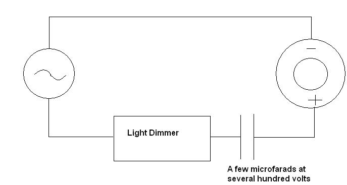
                              • This is a simple circuit using a dimmer to drive an ignition coil, could we also drive a mot with it.
                                Half of the Answer is knowing the right Question

                                Comment

                                Working...
                                X