 Tweet
Tweet
I'm giving up, off to other things.
-
-
You had a cool setupOriginally posted by drak View Post
I think the problem is combining the two particles to get usable electricityHalf of the Answer is knowing the right QuestionComment
-
Thanks! Could be, I'm not sure what the problem was, or if it's even possible. I just tried lots of things and couldn't get ou. So until someone shows a promising DETAILED one thats working, I'm off to other things.Originally posted by Dave45 View PostComment
-
Reply
FEhunter,
sorry for the late reply.
I use a FLB from a computer monitor CRT (LG).
As a spark gap i use a sparkplug, and need to close the gap to 0.5 mm or so to reach 12Khz.
Using 10V being pulsed by a fet circuit.
Anyway, you said:
But it is even worse.So I calculated XL which is XL = 2 * pi * 34482 * 218E-6 = 47 Ohms.
and that means that you are right. This impedance is to low for my FLB.
You are right about this XL being 47 Ohm on 34482Hz, but also XC on 34482 is 47 Ohm
as we are in resonance, meaning that Xl and Xc are canceling each other out (180 degrees out of fase).
So we are left with the Impedance Z being the R of the LCR which according to you is 0.5 Ohms
No way to get a NST or FLB to work on a 0.5 impedance circuit.
You need to increase the resistance of the used coil for them to work or better to keep a series spark gap.
References:
http://users.telenet.be/marcel.adria...allelkring.xls
http://users.telenet.be/marcel.adria...SERIEKRING.xls
http://educypedia.karadimov.info/library/wissel.pdf
page 36
Regards ItsuComment
-
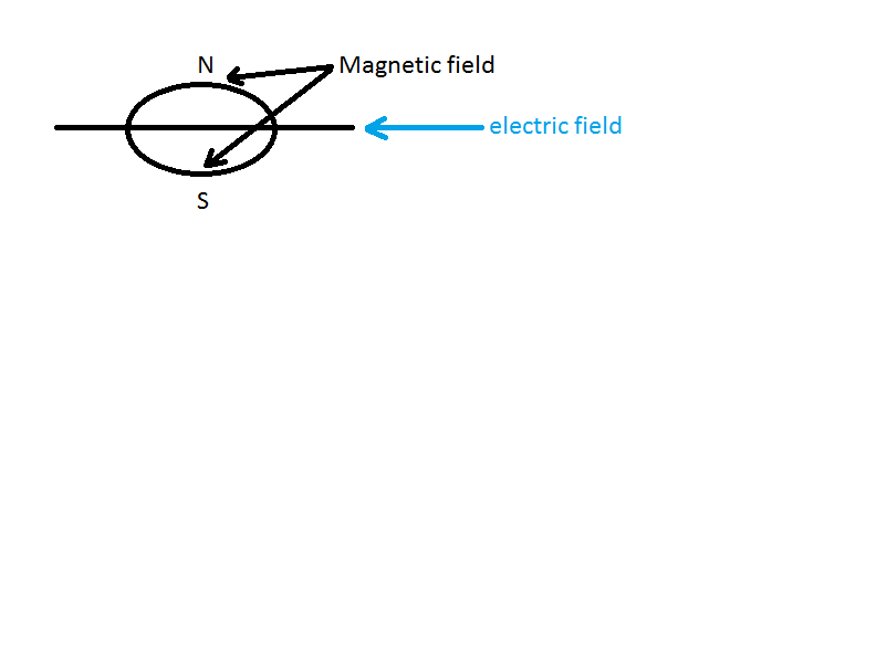
Which end is up?
Originally posted by Dave45 View Post
Does it matter which hemisphere you are in?
And, primary to secondary cw to cw, or cw to ccw? Dude, you're curving my space-time.
Comment
-
Exactly, I think (not tested) the north is cw and south is ccwOriginally posted by deggers View Post
Since we are in the northern hemisphere cw would be coming out and ccw would be going in so place the primary with south down, secondary with ccw down,
This is something that I would think would be critical with this device the primary has to be the right polarity compared to the cw,ccw secondary
Placing the unit vertical would clean up the fields.Half of the Answer is knowing the right QuestionComment
-
If we look at ufo tech the saucer is always horizontal even during lift here's why
depending on which hemisphere your in would determine whether south was down or north was downHalf of the Answer is knowing the right QuestionComment
-
An improved design
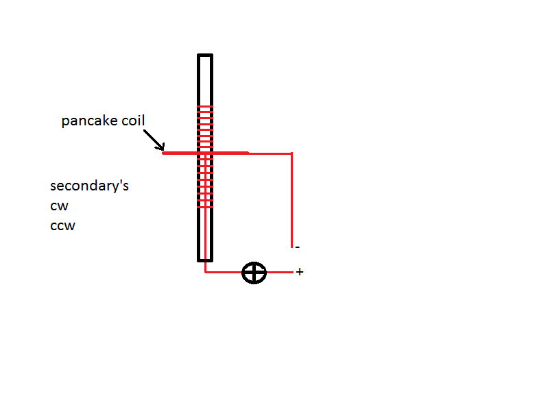
If you look at the pancake one side is cw one is ccw wind the secondary's accordingly.Half of the Answer is knowing the right QuestionComment
-
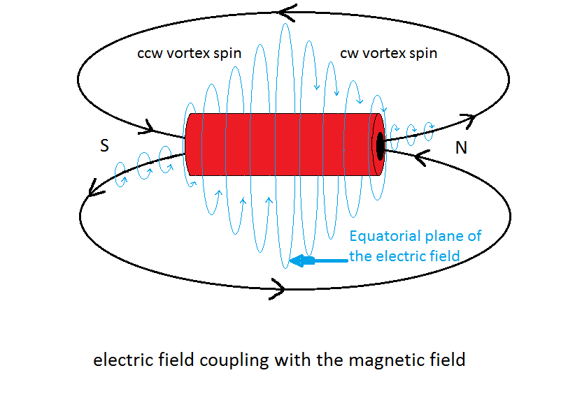
Screen wire shields radio frequency these fields are in that range they can be shielded, shield inside of core this makes the fields run to outside to connect with the magnetic field, it makes them run along the secondary's.
Another idea fix a flat shield at the end of secondary's, a square with a hole for the tube out of screen, as the field travels along the secondary's it will be blocked by this shield, this shield could be glued or sandwiched between acrylic sheets.Half of the Answer is knowing the right QuestionComment
-
I was hoping to get a message to magnetflipper to ask if he noticed the polarity of his magnets in this vid to determine the spin directions but it seems his channel has been removed from govtube.
MAGNETIC VORTEX SPIN DISCOVERY, Sept 2011, TORNADO UNDERWAT mp4 SD - YouTube
 Last edited by Dave45; 10-24-2011, 12:23 PM.Half of the Answer is knowing the right Question
Comment
-
 Half of the Answer is knowing the right Question
Comment
-
What do you think of that? Maybe is from Kapanadze?Originally posted by Dave45 View Post
We must discuss about that schemes, can be what we are looking for.
Tariel Kapanadze SECRECY / FreeEnergyLT / FreeEnergyLTComment
-
nice link you provided...Originally posted by nico View Post
ps: Dave, you should check it out, you'll recognize a few of the principles you talk about in the various experiments presented (not just kapanadze, the others too )
)
�Signs and symbols rule the world, not words nor laws.� -Confucius.
Comment
-
L2 Coil Split
Just a thought. Don said that L2 should split the current and voltage based on CW and CCW orientation. I'm thinking that L2a (volts side) should look very inductive, while L2b (amps side) should look very capacitive. Based on the schematics that I have seen, both sides look the same except for winding direction.
L2a output could have additional coil placed in series downstream to increase inductance, while L2b would have an additional capacitor in parallel before the two are joined together.Comment
-
post 1289 page 43
Hi Itsu,
Don't feel compelled to your late reply. Me too, I don't have time to watch the posts every day. I assume that your driver does not drive your FLB so that its frequency is higher. Because it should be. Here is a link to a ZVS driver I use. Teravolt.org - ZVS Driver
You can vary the capacitor of .68 uF and you can wind fewer or more turns to the FLB to vary the output frequency.
Thank you for the links. It's allways nice to see how others program their applications. I program my own application when I need something. Sometimes it is in Excel, sometimes in Matlab or Mathcad. It depends why I need the output for. The math of the book approaches my borders of knowledge. Especially complex calculations. Then I really need to concentrate.
But to stick to the Don Smith device, do you think the parallel LC circuit will provide OU so that a device could be build to power our homes? I think the principle is quite logic to me and it is not beyond my skills to build it this way. I'm going to realize that the components should be perfectly tuned to each other in order to have the device working.
So you state that a LC parallel circuit at resonance the Xc an Xl cancel out each other leaving only an ohmic component which is to measure with a multimeter. In my setup this is .5 Ohm which is to low. How could Zilano say that in her LC the spark gap fires. It looks impossible with only 80 turns. As I understand the spark gap only fires when the capacitor is being charged and then discharges over the coil.
I'm trying to use the secondary of a car ignition coil. The one I have has a DC resistance of 5300 Ohms and its L is greater than 1 H which is the limit of my LC meter and it has a lot more turns than 80. I only have to think how to find the L. Do you think this is worth to try?
regards
FEhunter
Comment

Comment