Announcement

Collapse
No announcement yet.

Donald Smith Devices too good to be true

Collapse
X
 
  • Filter
  • Time
  • Show
Clear All
new posts

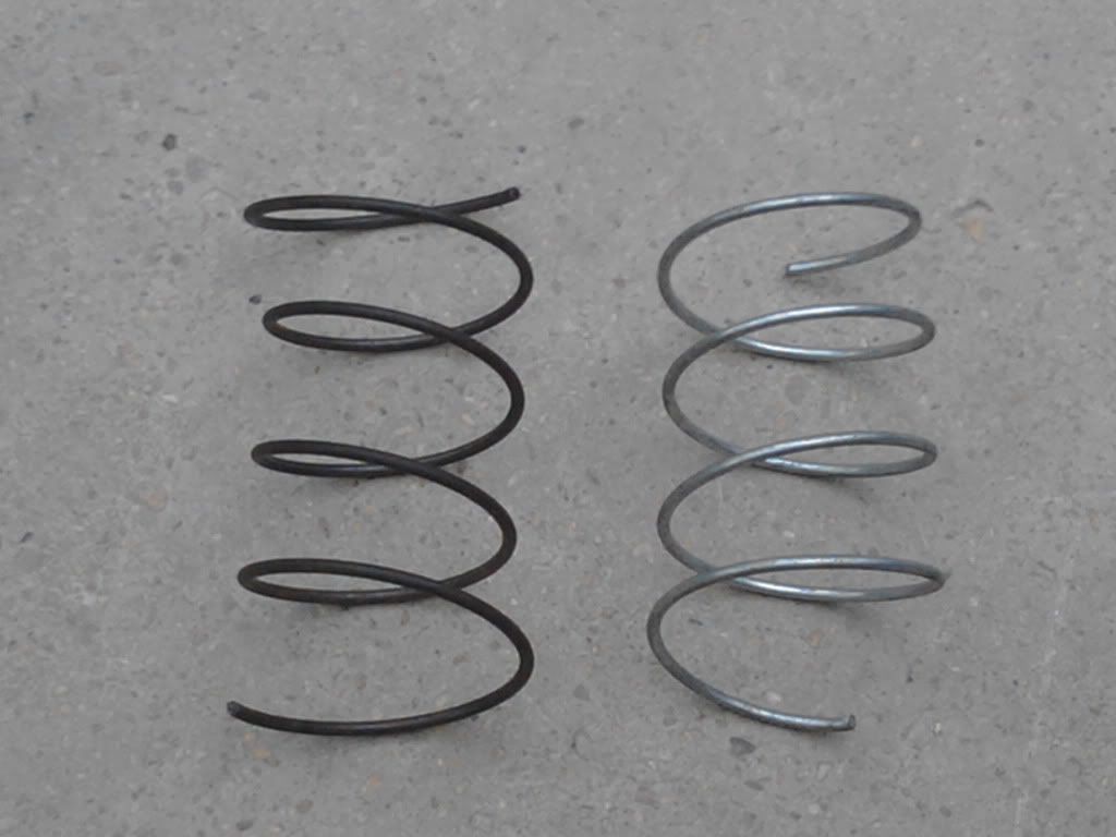
  • When I look at this diagram I see that the direction of turn wrap (curved arrow)
    of the Amps arrow is the same as the volts arrow, the only difference is the end
    the arrow point is on.

    If the coils needed to be opposite wound then this diagram should show a mirror image of the curved arrows, indicating the turn wrap direction to be opposite.
    But it doesn't .

    The two curved arrows show the same wrap direction in this diagram, just different force directions.


    Uploaded with ImageShack.us

    Cheers

    Comment


    • Yea my drawing in mpaint is lacking
      Here's a pic of two opposite wound springs

      This should give everyone a better perspective.
      Half of the Answer is knowing the right Question

      Comment


      • If we look at creation all around us we see the opposite spin directions, one of my favorite is mining of quartz for crystal radio's they prefer the cw spin direction for their crystals and dont use the ccw spin quartz.

        The sun flower show's both spin directions in its design.

        The evidence is all around us we could go from example to example
        Half of the Answer is knowing the right Question

        Comment


        • Originally posted by Dave45 View Post
          If we look at creation all around us we see the opposite spin directions, one of my favorite is mining of quartz for crystal radio's they prefer the cw spin direction for their crystals and dont use the ccw spin quartz.

          The sun flower show's both spin directions in its design.

          The evidence is all around us we could go from example to example
          But why do you equate opposite spin direction to opposite winding of the coils ?

          The diagram I posted shows opposite spin direction on the same winding direction
          ie. the same piece of wire wound into a long coil when excited in the middle the current amps go one way the electron volts the other.

          When you put two opposite wound coils end to end they are a mirror image of
          each other and so different to the diagram of Dons to explain it.

          Both coils in my opinion should be wound the same, or one coil cut in the
          middle to make the center tap then when excited in the middle the electron volts go one way and the current amperes go the other.

          Center tap as Dons drawing says.

          Like in the diagram, I don't see opposite spin as you put it needing to have
          opposite wound coils, I see it as needing one coil cut to make two coils and
          the center tap. Like Don instructs to do in one of his video's.

          Cheers

          Comment


          • Here's what I think after pondering it.

            The secondaries are wound the same way and when the primary is at the center
            tap it's like the "Bloch wall" and being connected to ground as a source of
            negative "charge", the center tap is an "input", both coil ends are connected
            together to one side of a FWBR and the center tap is connected to the other.

            Cheers

            Comment


            • Originally posted by zilano
              Hi folks!

              DECISION TO CHOOSE BUFFER CAPACITOR

              as we know C=Q/V

              C= FARADS
              Q=COULOMBS
              V=VOLTAGE

              A 2 MKFD @ 2000 VOLT CHARGED IN 1 SEC
              CAPACITOR CAN PROVIDE OR HOLD

              since 1mkfd=1/100000 farad

              Q=C*V
              Q=0.000002*2000
              Q=0.004

              SINCE 1 AMP= 1Q/1SEC
              WE HAVE .004/1SEC
              SO WE HAVE .004 AMP

              SO A CAPACITOR 2000 MKFD @ 2000 VOLT CHARGED IN 1 SEC
              CAN PROVIDE OR HOLD
              Q=C*V
              Q=0.002*2000
              Q=4 /SEC

              SO 4 AMPS/SEC IS PRODUCED OR HELD

              AND 4 CAPS 2000MKFD RATED @ 2000 VOLTS CAN PRODUCE
              4*4= 16 AMPS CONTINUOUSLY PER SECOND

              This depends on how your circuit is made: series or parallel.
              4 caps series has 500 MKFD @ 8000 VOLT
              4 caps parallel has 8000 MKFD @ 2000 VOLT
              So you should calculate you output first (voltage and amps), then calculate the cap(s) for it?


              SINCE P=V*I
              POWER PRODUCED
              P=2000*16
              P=32,000 OR 32KW SEC
              OR 32K JOULES

              REGARDS

              ZELINA
              Originally posted by zilano
              addition to caps calculation thing

              apply formula

              0.5*c*vsquared.f <=>
              0.5*c*vsquared.*(f)^2 f=1

              The above COMBINED with a "resonate energy induction system" (all electrons moving at the same time in the same direction), make the next move into overunity practical.
              This overunity device produces energy at radio frequency ranging into the megahertz range. At radio frequency the Electrons do not pass through the conductor as at lower frequencies. These Electrons encircle the conductor and are free of the conductor's resistance.

              According to Don Smith (Resonate Tank Induction Energy Transfer System): W = 1/2 x C x (V)^2 x (freq)^2
              Joules = [1/2 x C x (V)^2] x (c.p.s)^2
              Joules = {Volts x Amperes x Seconds} Watt Seconds

              freq is squared!


              WHERE F IS FREQUENCY
              IF F IS 30KHZ
              THEN 30000 COULOMBS R TRAVERSING AND 120 VOLT IS VOLTAGE OF CHARGING
              SO A 2MKFD CAPACITOR CAN HOLD OR DISSIPATE

              .5
              .000002 ×
              120 ×
              120 ×
              30,000 ×
              --------------------------
              432 = JOULES SEC

              SINCE P=VI
              AND I=P/V

              432
              120 ÷
              --------------------------
              3.6 = AMPS PER SECOND

              SO 4 2MKFD CAN PROVIDE

              3.6*4=14.4 AMPS SEC AT 120 VOLTS


              RGDS

              ZZZZ
              Best regards

              Comment


              • Originally posted by TanTric View Post
                Hi T-100, 5Kv on only 1 Winding secondary? thats really impressive...

                the secondary is also a caduceus?

                also your consumption of 6W is impressive, how much volts/amps are being draw in your system? your flyback puts out AC? how are you firing spark gap and charging the cap with only one wire? not shore if i understanded well...

                great! thank you for sharing!!
                Hi,

                Sorry for some delay, had hard work putting pieces together on the hunt for taking off that high voltage of cold electricity back into hot electricity...

                The primary is caduceus - http://drblayney.com/images/jbwnd.jpg Caduceus vs Staff of Asclepius It's function is to generate scalar (torsion) rotating magnetic field.
                The 2 secondaries is like 2 Tesla coil secondaries: primary plus each secondary coils masses are equal, the secondary is not longer than 1/4 of resonant frequency wave length.

                Both secondaries are wound with left hand+right hand sides from the center to the ends of tube. The most active zone is in the center.
                The capacitor and spark gap for primary is fed over 1 wire from flyback transformer over 2 diodes (the flyback transformer itself is in resonance and it's ferrite core is grounded). The "cold" end of flyback transformer comes back to junction of 2 secondary coils in the center (we have open circuit with capacitive action between coils).
                The ferrite inside of coils is insullated in the center (otherwise it ends heading up and emitting energy out).

                Also the corner stone concept is: the Nature always havе duality - 2 opposites what neutralize energy states in mattery. While in electricity that means we're using hot and cold electricity and to make that we use opposite windings for transforming conventional magnetic field into scalar (torsion) magnetic field. This results cold electricity what we use to regain hot electricity. Please see all Nicola Tesla writings and patents, the truth is buried over there(see what he was repeating over and over again).

                P.S> Probably there will be full video over few days, please be patient...

                Comment


                • Thanks T-1000; If i may add, it is also buried in the schematics of Tesla's Set up


                  isn't it Farmhand

                  Originally posted by Farmhand View Post
                  I found a better drawing of the magnetically quenched spark gap Page 306 of the IRWNT book. looks like just a coil with a lot of wire and the poles are extended so the coil is far enough below the gap and the added pole piece projections are adjustable and shaped.


                  Uploaded with ImageShack.us


                  Cheers
                  Farmhand, notice the endings of each pole..."2 cones" and a " a disc" if viewed sideways

                  Last edited by MonsieurM; 10-14-2011, 12:19 PM.
                  Signs and symbols rule the world, not words nor laws.” -Confucius.

                  Comment


                  • Originally posted by Farmhand View Post
                    Well the open capacitor is "not" meant to be the receiver, like I said the energy is transmitted through the ground not through the air.

                    The transverse waves are shielded yes, but the energy is not going from one open capacitor to the other through the air in the form of longitudinal waves.

                    If they are close together there might be some capacitive coupling. Which I don't think a faraday cage will shield from either, not sure.

                    This is from Tesla's court case, Under oath. Source of quote.


                    So Tesla says that long distance radio reception is more due to Earth currents than radiations of electromagnetic waves.


                    How can the two resonant points be verified ? I'll watch the video again.

                    My advice is to study the inventors information (Tesla) not the copiers information (Meyl). It's too easy for them to slip people little furfies.

                    Cheers
                    Hi Farmhand,

                    Point(s) taken!

                    So Don Smith used a different type of system to "pump or extract" excited electrons nearby in it's earth and air and groundings due to flux lines at the top end of L-two.

                    Best regards

                    Comment


                    • Originally posted by cognito View Post
                      Hi Farmhand,

                      Point(s) taken!

                      So Don Smith used a different type of system to "pump or extract" excited electrons nearby in it's earth and air and groundings due to flux lines at the top end of L-two.

                      Best regards
                      I'm not saying that, I'm just commenting on Meyl and the Tesla Wireless
                      transmission system. The Tesla wireless system Meyl chose to promote is the
                      older version. Why not promote the Magnifying Transmitter" System Which
                      was a later and better system ? It is possible I agree that some energy could
                      get into the system through the open capacitor terminals, but the
                      transmitted energy is meant to go through the ground not the air,
                      if energy can enter through the open capacitor it can also leak which is more likely.

                      ELECTRICAL ENERGY - Google Patents

                      I think Meyl says some dubious things. He says 1000 % efficiency but what
                      does that mean ? I can get 1000 % voltage gain from my setup but that
                      doesn't mean much in itself. Is he claiming he can get 10 times the energy out
                      that he puts in ? I doubt it. I can't say if Don's setup is for real or what it
                      does but if I were going to build one I wouldn't be so quick to cling to the
                      opposite wound secondaries thing. I would test both ways, but I would test
                      two wound the same first. But that's just me.

                      Cheers

                      P.S. I apologize for ranting Cognito, but that Meyl guy just annoys me for
                      some reason. Sorry.
                      Last edited by Farmhand; 10-14-2011, 01:12 PM.

                      Comment


                      • Originally posted by Farmhand View Post
                        I'm not saying that, I'm just commenting on Meyl and the Tesla Wireless
                        transmission system. The Tesla wireless system Meyl chose to promote is the
                        older version. Why not promote the Magnifying Transmitter" System Which
                        was a later and better system ? It is possible I agree that some energy could
                        get into the system through the open capacitor terminals, but the
                        transmitted energy is meant to go through the ground not the air,
                        if energy can enter through the open capacitor it can also leak which is more likely.

                        ELECTRICAL ENERGY - Google Patents

                        I think Meyl says some dubious things. He says 1000 % efficiency but what
                        does that mean ? I can get 1000 % voltage gain from my setup but that
                        doesn't mean much in itself. Is he claiming he can get 10 times the energy out
                        that he puts in ? I doubt it. I can't say if Don's setup is for real or what it
                        does but if I were going to build one I wouldn't be so quick to cling to the
                        opposite wound secondaries thing. I would test both ways, but I would test
                        two wound the same first. But that's just me.

                        Cheers

                        P.S. I apologize for ranting Cognito, but that Meyl guy just annoys me for
                        some reason. Sorry.
                        No problem Farmhand

                        Don wrote interesting information (clues) in his book:

                        "There are four major power sources providing enormous amounts of Ambient Background
                        Magnetic Wave Energy. They are The Cosmos, Galactic, Solar and Earth's Ambient
                        Electromagnetic Backgrounds. The Earth's Electromagnetic Field comes from reflection,
                        deflection and absorption as a result of Faraday's action at a distance from the above.

                        Magnetic Flux Background maps of the Earth's Surface yield important information regarding
                        reflection, deflection and absorption of incoming Magnetic Waves, plus action at a distance.
                        When properly understood, these maps yield a very large Ambient Electromagnetic Energy
                        Source. When deflected, Magnetic flux from electrons changes to Electrical flux, providing
                        the Motor System that spins / rotates the Earth... Absorbed microwave flux energy heats
                        from the inside out, therefore a hot interior Earth.

                        Wave Phenomenon associated with action at a distance...
                        All Electromagnetic Energy harvesting methods include a Catalyst, a Collector and a Pump.
                        Catalyst include sensitization (A process in which a given behavior increases in intensity
                        simply with repeated occurrences) through doping with certain elements, air and earth
                        groundings.
                        Collectors include temporary storage as in Capacitors, Coils and Transformers.
                        The Pump System Includes induced movement onward to point of use...

                        Direct access occurs when Magnetic Waves impact a catalyst, spinning the Local electrons sideways, producing useful electrical energy"

                        Best regards

                        Comment


                        • This looks like Dons explanation for the over unity energy present in the system. No big mystery. Just gotta read the documents.


                          Uploaded with ImageShack.us

                          In this diagram below there is a hint. It says volts dominate if the L1 is far right,
                          it doesn't make any sense to me that when the L1 coil is far right and the center
                          tap is to the left of the L1 that the direction of the coil winding reversing
                          would be a good thing. I think that if the secondary was wound two halves
                          opposite wound then when the L1 is moved to the right of center, then to the left
                          of L1 would be a section of coil with a winding direction reversal.

                          But I think that if wound both the same this would not be a problem.


                          Uploaded with ImageShack.us

                          Comment


                          • The video is out in the wild now
                            International Friends for Tariel Kapanadze working OU!!! - YouTube

                            (I am Arunas there)

                            Have fun watching and try to understand principles as much as you can. If you will want to replicate this, you need to be human with brains and tools, not just like monkey repeating circuit!

                            Comment


                            • Originally posted by zilano
                              What is caduceus coil? Can replace caduceus coil with bifilar coil? Is the same?

                              Comment


                              • Originally posted by zilano
                                if we take F^2 fully then resonance condition is lost. so we take one f only and other f is used to maintain resonance. fetching power with resonance maintained.

                                rgds
                                Hi,

                                What I understand...
                                The L2 bottom cw coil on resonance is "powering" the L2 top coil on the same resonance? Power is f for L2 bottom and f for top coil (combined f^2), so f useable is not f squared but only f, what you calculated above ?

                                Best regards
                                Last edited by cognito; 10-14-2011, 07:16 PM.

                                Comment

                                Working...
                                X