If this is your first visit, be sure to
check out the FAQ by clicking the
link above. You may have to register
before you can post: click the register link above to proceed. To start viewing messages,
select the forum that you want to visit from the selection below.
Now do following 2 experiments while changing primary coil:
Wind Caduceus coil and put your secondaries on sides and wind counter-bifiler and try it again.
Now do following 2 experiments while changing primary coil:
Wind Caduceus coil and put your secondaries on sides and wind counter-bifiler and try it again.
Why would I want to do that? That has nothing to do with Don Smith. I try lots of things, I just don't video record it all. Have tried CW-CW They just cancel each other. CW-CCW works.
Ok, in this video I was floating my battery with the power supply, I had the current limited on the power supply 2A 13.4v. So when powering the device the battery was staying charged because of the power supply. The bulbs I was playing with was 12v DC 50watts. Input to the system was 12-27 watts adjustable with the spark gap. I went like Zilano said directly from the nst to a step down. Adjusting the spark gap also adjusts output voltage because it was a series spark gap.
The weird thing about the output, is the voltage level on the scope before the full wave bridge and after it. BEFORE the FWB, I get only about 70-170 (adjustable) volts. AFTER the FWB I get about 250 to I'm guessing 1000v (adjustable). Maybe someone can explain that. Before the FWB I get the standard ring down waveform. After the FWB, I get the ring up waveform. The bulb seems to be a little dimmer though after the FWB then before. Standard 120v bulbs will not light at all, not even the little 6 watt one I have however a 12vDC 50watt bulb will? Confused. Maybe the bulbs are frequency dependent? Both coils were resonant at 32.9khz (which took almost every capacitor I had). I used a ferrite core made of the little rods you seen in the video, I just taped them all together to make a bigger rod. BTW, use insulation on your ferrite core, I forgot the ferrite can shock you.
Near the end of the video I took the other bulb same wattage and ran it directly from the power supply. It was a little dimmer then output from the smith coil. Thats a plus I think. The camera really makes the bulbs look brighter then they are. Primary was 14 guage house wire 46 turns 20 feet, and the secondary was the 8 guage jumper cable wire 3 turns 5 feet each coil. Slowly getting there.
Thanks for all your help Zilano. I'm just a slow learner.
I believe is about impedance of secondary coil must be the impedance of the bulb, that way they make DC current and have caps in secondary.
The resonance is very important too. Look how this one make resonance in secondary coil, no caps for that. 0826103613Composite.avi - YouTube
He use natural frequencie of the coil
He establishes resonance; between ground and middle of coils have a signal generator. The two probe of oscilloscope have wire, one turn, on each sides of secondary. The coils are the same, just 0,2-0.4 inch differences .
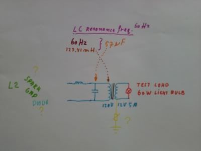
Can I use just a standard 120v to 12vdc transformer as a isolation just for testing? I have a bunch of them, or do I have to make my own? I measured 123.41mH for the input to a transformer I had laying around. That gave me:
57.014774 uF cap
I thought maybe Drak wanted to try this posibility.
I am still wondering how Don would have done it .. and of course what you, Zilano think of it.
I am realy enthousiast and thankfull of all your info, it helps me understand the technique and so I will also be able to perform miracles.
Why would I want to do that? That has nothing to do with Don Smith. I try lots of things, I just don't video record it all. Have tried CW-CW They just cancel each other. CW-CCW works.
Hello Zilano and Drak,
I thought maybe Drak wanted to try this posibility.
I am still wondering how Don would have done it .. and of course what you, Zilano think of it.
I am realy enthousiast and thankfull of all your info, it helps me understand the technique and so I will also be able to perform miracles.
Attached is bigger picture.
Hi,
This is what I understand how it should be connected.
Use varistors to limit the voltage and protect the transformer (everyone's feedback is appreciated)
you really are confusing zilano, first you sayd for drak not to use resistors, then you say to use a voltage divider that haves resistor's?
you sayd to use 2mfd caps, is not the value of the caps dependent of the coils inductance so we get ressonance at 60Hz?
why not to put the output of the secondary in the 220V side of the trafo, and then extract 12V? that will be a naice voltage to loop the system and disconnect the power source!!
just my point of view!
peace
Originally posted by zilano
enter 60 hz and enter the value of primary of ur trafo. it will give u tha value of cap dont use resisitor here coz u need 60 hz.zzzz
Originally posted by zilano
yes after fwbr use filter to bypass 33khz ripples and then use storage caps 2mfd rated for the voltage usevoltage divider to get 12 volt and use push pull after that. u can now use any 12 volt to 120 volt iron cored trafo.
Light, I Am!
You are Not a Body that has a Spirit, You are a Spirit that Has a Body! There is no Path to Peace, Peace is the Path!
Maybe use a welding transformer. Rewire the secondary for 12v. Most of them running 20 to 40 v out, lots of amps. Take a few turn off sec for 12v. U can get some with 120 primary and some with 220. Just my thinking for power output
you really are confusing zilano, first you sayd for drak not to use resistors, then you say to use a voltage divider that haves resistor's?
you sayd to use 2mfd caps, is not the value of the caps dependent of the coils inductance so we get resonance at 60Hz?
why not to put the output of the secondary in the 220V side of the trafo, and then extract 12V? that will be a naice voltage to loop the system and disconnect the power source!!
just my point of view!
peace
Hi TanTric,
You can do this different ways:
From buffer capacitor, lets say 2 milli-Farad = 0.002 F (DC in VAR!!!)
1. Use voltage dividers from buffercap(s) to get 12V, input 12V to inverter and use (230V to 12-0-12) or (110V to 10-0-10V) center tapped transformer connected in reverse. This will give output AC 230V or 110V.
(see inverter circuit 50Hz,60,400Hz )
or
2. Use isolation transformer AC (380 to 230V) or (230V to 12V for testing) on resonance 50Hz or 60Hz with surge-arrestor or sparkgap.
Connect capacitor to (iso)transformer to have (LC=resonance frequency) correct frequency etc. Calculate self-resonance.
Use varistor to protect the transformer, to limit the voltage (redirect current) from the transformer!
(everyone's feedback is appreciated)
Best regards
Will be a huge capacitor for resonance at 50-60 Hz.
i have a ferrite core (step down transformer, not "isolation", this is an old and rare one) that can provide 12V at 10A with 220VAC input... i will use this one and not iron core because im using flyback and TC with ferrite core to. i have a frequency generator circuit so i can tune the best frequency. i will follow option 2, a step down usually have also isolation windings right?
it haves writen "high potted" (dont know what it means, maybe that allready haves a varistor^?)
the (0.002F) buffer capacitor that you mention does not need a value to be in ressonance with the secondary of TC to? sory so much questions
From buffer capacitor, lets say 2 milli-Farad = 0.002 F (DC in VAR!!!)
1. Use voltage dividers from buffercap(s) to get 12V, input 12V to inverter and use (230V to 12-0-12) or (110V to 10-0-10V) center tapped transformer connected in reverse. This will give output AC 230V or 110V.
(see inverter circuit 50Hz,60,400Hz )
or
2. Use isolation transformer AC (380 to 230V) or (230V to 12V for testing) on resonance 50Hz or 60Hz with surge-arrestor or sparkgap.
Connect capacitor to (iso)transformer to have (LC=resonance frequency) correct frequency etc. Calculate self-resonance.
Use varistor to protect the transformer, to limit the voltage (redirect current) from the transformer!
(everyone's feedback is appreciated)
Best regards
Light, I Am!
You are Not a Body that has a Spirit, You are a Spirit that Has a Body! There is no Path to Peace, Peace is the Path!
this will produce 60 hz ac but it is intermittant(depending on spark frequency) with a break in 60 hz wave. its is useful to light bulbs with break. break not apparent but for inductive loads and electronic equipment we need continuous wave ac 60 hz thats only possible with push pull or invertor.
Or maybe we need a modulation of 35Khz with 60Hz like this:
 Tweet
Tweet


Comment