Announcement

Collapse
No announcement yet.

Donald Smith Devices too good to be true

Collapse
X
 
  • Filter
  • Time
  • Show
Clear All
new posts

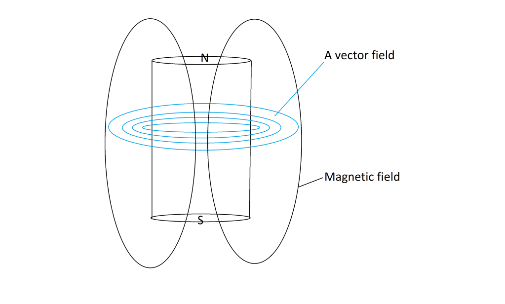
  • Here's the A vector field of a magnet or coil- the primary in Don's device

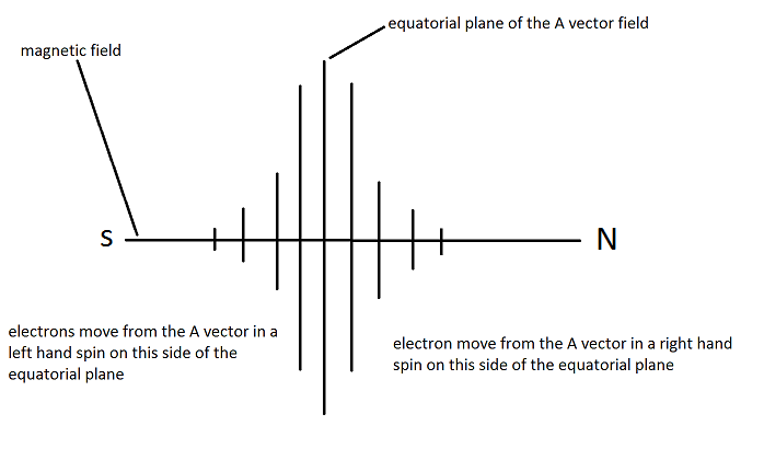
    Here's how the A vector field couples with the magnetic field- and in Don's device the secondary

    Dave
    Half of the Answer is knowing the right Question

    Comment


    • Originally posted by drak View Post
      Farmhand,

      I will test the CW-CCW thing. Currently I have two full waves CW and CCW, drying. Then I will try two full waves both CW. Is that what you are talking about? I'm actually getting pretty good at making coils. I am the coil maker!
      Yeah that's what I meant, just saying the best way to find out for sure is to try it both ways with the same setup.

      And the direction of pulsing the primary could have an effect also, maybe with some setups I've seen you guys have (good setups) it would be easy to reverse the primary just to see what happens with that too.

      I have a setup for lighting (not finished) with two clockwise secondaries (center tapped) and two primaries so I can test these things, but I can't pulse it at high enough frequency for resonance yet, best I can get is a low harmonic I think, I think I need about 4 or 5 Mhz. I can test just by output but that's not so accurate.

      My equipment is poor and I'm just learning too.

      .

      Comment


      • Originally posted by dragon View Post
        Consider the reversed voltage of this coil diagram. When the coil falls to a negative voltage what happens at the earth ground? Wouldn't the ground then become the source?
        I think you got a point, maybe it's then that you can pump electrons from the earth ground. It's like the earth is a big reservoir of negative charges and they need to be disturbed.

        Comment


        • Originally posted by dragon View Post
          Consider the reversed voltage of this coil diagram. When the coil falls to a negative voltage what happens at the earth ground? Wouldn't the ground then become the source?
          Dragon where did you took that picture, could you send the adress please.

          Comment


          • Originally posted by dragon View Post
            Consider the reversed voltage of this coil diagram. When the coil falls to a negative voltage what happens at the earth ground? Wouldn't the ground then become the source?
            I can't quite make out the words in the diagrams and exactly what it represents.

            But I think I know what you mean. In Dons device I "think" the earth ground when connected to the center tap will make the center end of both coils negative and referenced to the ground, but the spin direction of the coil turns will not change from one secondary to the other going all the way from one outer end to the other outer end. Although the polarity will flip in reference to the ground. and therefore create an up + and down - from 0 volts ground reference at each outer coil end.

            So the voltage is not actually doubled this way so the only other thing is more current possible, and by moving the primary back and forth "up and down" the ratio is changed between the opposing voltages and therefore the current possible also is changed. I think, But resonance is maintained even though the output is manipulated.

            Rather than the currents from the secondaries flowing back into themselves they can flow into the ground and back in a couple of places I think.

            I don't have any solid full picture but I intend to not overlook anything if possible.

            What do you think about my explanation ?


            P.S. The voltage is not doubled because the earth ground is connected to one side AC of the FWBR and the Two outer ends to the other AC of the FWBR so there is both + and - voltage supplied to one side at the same time.

            Well that's what I'm thinking so far, because I just can't go straight past Don saying to just cut the one long coil to center tap it. Not without testing it.

            ..
            ..
            Last edited by Farmhand; 09-18-2011, 03:23 AM.

            Comment


            • Originally posted by Farmhand View Post

              I have a setup for lighting (not finished) with two clockwise secondaries (center tapped) and two primaries so I can test these things, but I can't pulse it at high enough frequency for resonance yet, best I can get is a low harmonic I think, I think I need about 4 or 5 Mhz. I can test just by output but that's not so accurate.

              My equipment is poor and I'm just learning too.

              .
              Well, my pulse only goes up to 3mhz, but my sine wave goes up to 20mhz. A trick I found for finding resonance of a coil without spanning the whole frequency spectrum, is to pulse one coil with gen near the coil you are checking with 1khz pulse, and watch the other coil directly on the scope. Zoom in on the pulses and you can see the resonant frequency.

              I'm in the same boat, I would only be able to check by output too on how bright the bulb would be, but i'll try it anyhow.

              Comment


              • Originally posted by drak View Post
                Well, my pulse only goes up to 3mhz, but my sine wave goes up to 20mhz. A trick I found for finding resonance of a coil without spanning the whole frequency spectrum, is to pulse one coil with gen near the coil you are checking with 1khz pulse, and watch the other coil directly on the scope. Zoom in on the pulses and you can see the resonant frequency.

                I'm in the same boat, I would only be able to check by output too on how bright the bulb would be, but i'll try it anyhow.
                Same boat but you're setup is better. Whatever you can find out will be helpfull I think.


                P.S. I'll try a couple of things later and see what happens, If I can get any definite indication that is. Lets experiment.

                Comment


                • Ok I hooked up one of my nst's to my new coil. Alot brighter bulb then pulsing the fly back. With the scope wand in the air around the coil this is the scope shot I'm getting. Thats CW-CCW. I'm not sure what the frequency of the nst is yet, but it seems the more capacitance I add to the primary and secondary, the more energy i'm getting. Still more testing to do.
                  Attached Files

                  Comment


                  • Finding resonant freq.

                    Originally posted by drak View Post
                    Well, my pulse only goes up to 3mhz, but my sine wave goes up to 20mhz. A trick I found for finding resonance of a coil without spanning the whole frequency spectrum, is to pulse one coil with gen near the coil you are checking with 1khz pulse, and watch the other coil directly on the scope. Zoom in on the pulses and you can see the resonant frequency.

                    I'm in the same boat, I would only be able to check by output too on how bright the bulb would be, but i'll try it anyhow.
                    So you are saying if we pulse "A" coil next to the coil we are going to use in close proximity to it, we can measure the resonant freq. of the coil we are probing with our scope?
                    and find the resonant freq.
                    Ze said we can either force our chosen freq. as she did by using an oscillator. with a simple sign wave.....

                    humm that is your way. nice
                    Ze was explaining all we needed to do would be to get the freq to 234 Mhz by using the 1/4 to 1 rule? or 4:1

                    I got totally lost.
                    I have been studing the dr stiffler ways to srf and SRF so I have most of the baces covered with these three different methods.

                    there are so many ways to do this I need to quit talking and start doing and testing.

                    I have added more picture files and some other goodies I had collected while collecting date about magnetic resonance


                    Purfect practice makes purfect!

                    h2ocommuter

                    Comment


                    • Originally posted by h2ocommuter View Post
                      So you are saying if we pulse "A" coil next to the coil we are going to use in close proximity to it, we can measure the resonant freq. of the coil we are probing with our scope?
                      and find the resonant freq.
                      Yes, and if you add caps to the coil you are probing, you will see the resonant frequency changes, I just got used to doing it that way, probably easier if you just use an LCR meter and use the online calculator.

                      Comment


                      • looks like the saw tooth Don talked of....

                        Originally posted by drak View Post
                        Ok I hooked up one of my nst's to my new coil. Alot brighter bulb then pulsing the fly back. With the scope wand in the air around the coil this is the scope shot I'm getting. Thats CW-CCW. I'm not sure what the frequency of the nst is yet, but it seems the more capacitance I add to the primary and secondary, the more energy i'm getting. Still more testing to do.
                        That also looks like a purfect parametric oscillation. I see you have duel probes can you look at the input and the output at the same time?


                        Looks awesome to see if it is...

                        Just excited nice work...

                        Comment


                        • Originally posted by h2ocommuter View Post
                          That also looks like a purfect parametric oscillation. I see you have duel probes can you look at the input and the output at the same time?
                          Do you mean the input to the NST? Yeah, I assume it would be just a solid 12v. I don't have high voltage probes so I can't directly measure the primary input without frying my scope.

                          Comment


                          • what a hoot

                            Originally posted by drak View Post
                            Do you mean the input to the NST? Yeah, I assume it would be just a solid 12v. I don't have high voltage probes so I can't directly measure the primary input without frying my scope.
                            oh it is funny for some reason I think people are thinking what ia am thinking and I go off running..

                            allright I was thinking your scope was duel probe and such you could float one probe by the HV and the other one wherever the output signal was comming from and overlap them to see if it was overunity multiplcation.
                            Thus the parametric or parabolic oscillation.
                            No, that would probably be at the Ze bifiler... she wanted us to look at the cw wound center taped first; that is what you got the scope shot of right?
                            Irregauardless that does loook like what Don discribed as a sawtooth type of signal. but with + and - voltages......?


                            your doing good man.. steady as she goes....


                            Dragon how is your bench comming along?


                            zane

                            Comment


                            • Originally posted by h2ocommuter View Post
                              she wanted us to look at the cw wound center taped first; that is what you got the scope shot of right?
                              Irregauardless that does loook like what Don discribed as a sawtooth type of signal. but with + and - voltages......?
                              What I'm currently using is CW and CCW both full wavelength. I move the scope probe all over and I get that same scope shot, it just gets bigger or smaller. I disconnect the coils all together and grab a shot of of just the nst throwing a plasma charge, I'm getting a constant 32.8khz, no reverse triangle...well, at least I know the freq of my nst. I'm guessing that waveform is from the coils.

                              Comment


                              • Your experience is very important ! Can you post a picture how you placed everything ? First I'm very interested how you was able to measure frequency of NST from plasma discharge ? Do you mean spark gap ? How is it combined with NST ? I'm asking because I thought that it is impossible to measure output frequency that way because if I short my flyback with spark gap it seems to change frequency depending on air gap.

                                Second - I think - you are "in bussiness" like Don Smith said ! Your scope shots have shown resonant rise as pictured in Don video from 1996.

                                I think this is very important because one of the main problems with Don setup is spark gap - there is no resonance in primary due to spark gap acting as a "dirty hole" spreading energy in sound and light around. It's like a swing , when a few people trying to push it from two sides and it simply cannot speed up because they are not "synchronized".

                                If your spark gap is no messsing with frequencies then it may work like it should - to break at the peak of wave - this is imho the most important stage eveybody is failing at.

                                Comment

                                Working...
                                X