Announcement

Collapse
No announcement yet.

Donald Smith Devices too good to be true

Collapse
X
 
  • Filter
  • Time
  • Show
Clear All
new posts

  • Originally posted by drak View Post
    Well, my function generator replaces the 555, and I didn't think there was a difference in an ignition coil and a HV fly back except the flyback has a built in diode. Unless of course the ignition will handle more watts. Maybe thats another possibility. Maybe I'm not throwing enough power at it. Maybe it takes at least a certain amount of watts before it starts outputting more then input... good call!

    I think Zilano just wanted to disappear for a while.
    Hi Drak, i dont think that there is a difference between the 2, i think that the most important thing is to really know the frequency of utilisation so you'll be able to calculate the cap and adjust the coil. what is your frequency of operation, they told to have a freq above 20 khz but did they mentionned a max. frequency ???? and like zilano said, if youre at the point of resonance, the reactance in your circuit is extremely low so all the amps you push in the primary with bifilar, i think you will have some juice in the secondary.

    I'm building my hv stage and start experimenting.

    Comment


    • Originally posted by drak View Post
      OOPS.....

      I messed up, That IS supposed to mean In parallel. errrrrrr.

      Well, the circuit is wrong, and my post is wrong, but for some reason I can't edit that post.... Those caps are in parallel, ugh

      Thanks for the heads up.

      and no, its 5 feet primary.

      Correct circuit link: ImageShack® - Online Photo and Video Hosting

      drak
      If you wanna to insert the schematics in your post, just right click on your picture and copy link location ,paste it in your post and use insert image button and after that preview...if you done correctly your image will appear in your post...if you want to modify your post after you posted already ,click Go advanced button ;if you will click just edit button, your post will not be modified
      Hope this helps...

      Comment


      • Originally posted by Aaron View Post
        I have received a few messages about some pages "disappearing". This has nothing to do with the moderators of Energetic Forum.

        The only thing I see are message that have been deleted by the very member(s) who posted them. If someone deletes a message that they posted, that is their right.

        My suggestion is to make a copy of anything of interest while you see it in case it ever does get deleted.

        All 32 pages are in google cache:

        http://webcache.googleusercontent.co...ient=firefox-a

        I'd recommend someone going to each page and copy and pasting each post into a long word document, converting it to PDF and posting that document for everyone. But better hurry before the cache gets updated with fewer pages or is deleted itself. You can't trust web archives anymore.

        Good luck.


        I tried to find Zilano attachments he posted ,using cache method
        but most of them are lost .You can find just his text post and some few pictures...

        Comment


        • If Zilano deleted the attachments they will be lost. Google only indexes that text and programming of the page, they don't index and store actual files usually. Occasionally you will be able to find a pdf but not an image... unless you get lucky searching for it through images.google.com

          BTW, here is a site that will convert an entire webpage to .pdf
          Just enter the URL to the cached google page and it will convert it.

          Convert Web Page to PDF - #1 Web to PDF Converter
          Trust your own instinct. Your mistakes might as well be your own, instead of someone else's ~BW~ It's kind of fun to do the impossible ~WD~ From now on, I'll connect the dots my own way ~BW~ If I shall be like him, who shall be like me? ~LR~ Had I not created my whole world, I would certainly have died in other people’s ~AN~

          Comment


          • Some of the deleted posts

            Her are some of the deleted posts. I only saved up to a point.
            Last edited by nvisser; 10-07-2011, 03:25 PM.

            Comment


            • Originally posted by zilano
              Zilano, so you will keep on replacing your last 2nd post with evrything that you stumble upon in google ?
              How is this related to Don Smith thread?

              In the last weeks you have more confused people with all kinds of new theories, coil designs etc. than tried to do what they all really want, an explanation on how exactly YOUR 10 kW device works ...

              Deleting your posts is clear sign that you actually don't want anyone to know that.
              Makes people think why?

              Comment


              • Well, I got my nst's a little sooner then expected.... I guess they do show more output then input. Unless my math is wrong. Not sure why "Danger" is misspelled though.
                Attached Files

                Comment


                • Total Mastery Arrives...

                  ...when I know what to do with this link...


                  Coilcraft - RF chip inductor, power inductor, power magnetics, and other inductors

                  :-) Would anyone agree? Or is this not useful for tesla coilers? Just found it.

                  Comment


                  • Originally posted by Zlatko View Post
                    Zilano, so you will keep on replacing your last 2nd post with evrything that you stumble upon in google ?
                    How is this related to Don Smith thread?

                    In the last weeks you have more confused people with all kinds of new theories, coil designs etc. than tried to do what they all really want, an explanation on how exactly YOUR 10 kW device works ...

                    Deleting your posts is clear sign that you actually don't want anyone to know that.
                    Makes people think why?
                    Never mind the explanation, I just want a demonstration. Is there one ?

                    Comment


                    • Originally posted by Zlatko View Post
                      Zilano, so you will keep on replacing your last 2nd post with evrything that you stumble upon in google ?
                      How is this related to Don Smith thread?

                      In the last weeks you have more confused people with all kinds of new theories, coil designs etc. than tried to do what they all really want, an explanation on how exactly YOUR 10 kW device works ...

                      Deleting your posts is clear sign that you actually don't want anyone to know that.
                      Makes people think why?
                      That was my feeling too. If was genuine in the beginning, at some point she changed her mind and stated to sabotage the thread.

                      Comment


                      • OK here's what I think. Time to move forward in a logical manner.

                        I think someone should setup an experiment to see the difference between a secondary with CW and CCW turns in each half and a secondary with the center of a long coil tapped in the center to make the two halve's, so two CW in series.

                        I think connecting the hot end of CW coil to the hot end of a CCW coil in series with the center tap grounded they will cancel each other. Has anyone tested it with a function generator and scope. My function generator only go's to 3 Mhz.

                        Don says just tap the center of a long coil like his. Then calculate the length of one half of the total secondary or one individual secondary (one side) only. then divide that by 4 and make the primary that length.

                        And I think if each side of the secondary has for eg, 15 turns and the primary can be 3.75 turns with the extra wire for leads or something like that, any discrepancy between the resonant frequencies can be corrected with the cap sizing on the primary.

                        The tuning should be done for resonance with the secondary charging the big caps to be used to feed the output transformer.

                        The primary and secondary capacitance will need to adjusted for max resonance while it is actually charging the caps other wise it will be thrown out of max resonance by the big caps (the load).

                        There should be diodes on the positive of the NST outputs and the spark gap should be a series gap, the capacitor should be in parallel with the NST output with the spark gap between the negative of L1 coil (primary) and the negative of the capacitor.

                        I think the series caps and spark gap across the primary is for an AC source.

                        NST is DC, The HV diode's on the output/s of the NST are vital.

                        I can draw what i mean if anyone is interested to see Dons drawings copied by me. But drawn in a different style.

                        Cheers

                        Oh and the positive battery lead should have a diode and be 1/4 the length of the L1 coil.
                        Last edited by Farmhand; 09-17-2011, 11:44 PM.

                        Comment


                        • There is the possibility I could be wrong about the CW - CCW thing and that that is secret what Don was hiding, but I don't think so. I think it's simpler than that.

                          To explain what I mean, a bit better i hope.

                          If you cut a long coil in half then join the cut to make center tap, then use 1 primary and pulse it with DC the coils will be pulsed one up one down and they'll act like they are wound opposite ways even though they aren't.

                          Or to think of it another way, with a long CW coil cut for the center tap the primary will be positive towards outer end of one and negative towards the outer end of the other.

                          I think it needs to be investigated properly to find out one and for all the difference.

                          I think the big thing is that resonance has to be attained at maximum under the desired load. Not get it resonant first then connect load to secondary output. Loading the secondary will affect it's resonant frequency, if any capacitance is added to the secondary coil by the loading the secondaries resonant frequency will go down.

                          Cheers
                          Last edited by Farmhand; 09-18-2011, 01:34 AM.

                          Comment


                          • Farmhand,

                            I will test the CW-CCW thing. Currently I have two full waves CW and CCW, drying. Then I will try two full waves both CW. Is that what you are talking about? I'm actually getting pretty good at making coils. I am the coil maker!

                            Comment


                            • Originally posted by Farmhand View Post
                              There is the possibility I could be wrong about the CW - CCW thing and that that is secret what Don was hiding, but I don't think so. I think it's simpler than that.

                              To explain what I mean, a bit better i hope.

                              If you cut a long coil in half then join the cut to make center tap, then use 1 primary and pulse it with DC the coils will be pulsed one up one down and they'll act like they are wound opposite ways even though they aren't.

                              Or to think of it another way, with a long CW coil cut for the center tap the primary will be positive towards outer end of one and negative towards the outer end of the other.

                              I think it needs to be investigated properly to find out one and for all the difference.

                              I think the big thing is that resonance has to be attained at maximum under the desired load. Not get it resonant first then connect load to secondary output. Loading the secondary will affect it's resonant frequency, if any capacitance is added to the secondary coil by the loading the secondaries resonant frequency will go down.

                              Cheers
                              Consider the reversed voltage of this coil diagram. When the coil falls to a negative voltage what happens at the earth ground? Wouldn't the ground then become the source?
                              Last edited by dragon; 03-14-2012, 02:53 AM.

                              Comment


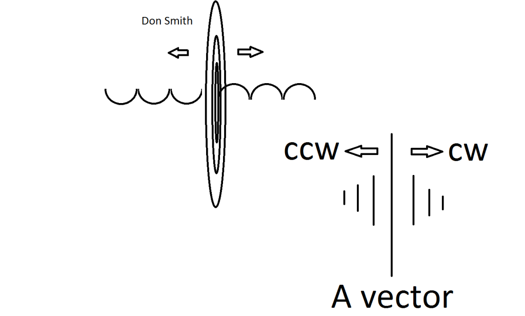
                              • Here's whats happening in the Don Smith device
                                the A vector in the primary is coupled to the secondary through resonance
                                The secondary is wound in such a way as to allow both spin directions to flow from the A vector of the primary into the secondary
                                Half of the Answer is knowing the right Question

                                Comment

                                Working...
                                X