Announcement

Collapse
No announcement yet.

Donald Smith Devices too good to be true

Collapse
X
 
  • Filter
  • Time
  • Show
Clear All
new posts

  • Barker & Williamson coil

    Hi, which Barker & Williamson coil would be better,@4 turns per inch . Airdux TL what would be 2404TL P/N or in the Miniductor the 3064 P/N . Thank You 4 your help
    Last edited by carmine; 08-16-2011, 02:04 PM.

    Comment


    • Originally posted by zilano
      Hi mike!

      solid copper thick coil. dont use hollow copper. think a transformer(induction) and make it tesla(resonance). i made a transformer and made it to resonate like tesla coil.
      consider how many amps u want in the output. and choose copper wire accordingly. if u need 5 amps. 5x110=550 watts or 5x120=600 watts. or 220x5=1100watts
      etc. hope u get my point! use wire according to amperage handling capabilities of the wire.

      regards

      zilano zeis zane!
      Hi Zilano

      I am looking at 50 amps min to 100 amps ideal, at 240v.

      2 awg is good to 94 amps for transmission and 181 amps amps for chassis wiring.
      American Wire Gauge table and AWG Electrical Current Load Limits with skin depth frequencies

      Stranded 2 awg is easier to form a spiral so I was looking at that for the secondary 5 thick turns. At 1/4" diameter it is also close to the Kapanadze single thick secondary.

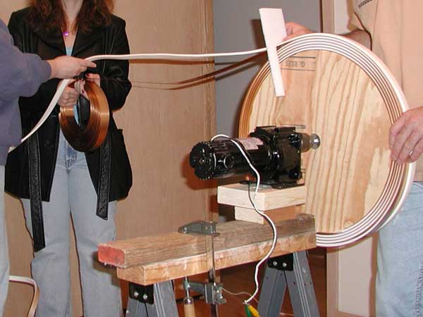
      Solid 2 awg copper cable would need a thin wide section for easy bending into a spiral. Like this 1.25" spring-bronze weatherstrip about 0.01" thick.
      Terry Blake's Huge Tesla Coil Primary


      Cheers Mike

      Comment


      • 1/4 copper tubing

        Originally posted by zilano
        Hi mike!

        solid copper thick coil. dont use hollow copper. think a transformer(induction) and make it tesla(resonance). i made a transformer and made it to resonate like tesla coil.
        consider how many amps u want in the output. and choose copper wire accordingly. if u need 5 amps. 5x110=550 watts or 5x120=600 watts. or 220x5=1100watts
        etc. hope u get my point! use wire according to amperage handling capabilities of the wire.

        regards

        zilano zeis zane!
        Oops, --- I was using 1/4 iinch copper tubing ---so I guess it's back to Home Depot to get some thick copper wire of sorts . I will probably opt for stranded as they don't have very thick solid stuff . I think we're getting close---let's keep going guys--Paul

        Comment


        • Here is a strange transformer with flat windings:
          tesla coil, primary inductor, copper wire base, wraps, taps


          I was always fascinated by Don's lectures and writings where his says his little table top coils/caps/resistors setup produces 30kw to 200kw of output to megawatts for country size units. So its all about the secondary wire size to being able to take the amps. Interesting indeed.

          Cheers Mike

          Comment


          • Ok I guess I am getting confused as to what you guys are referring to when you say bifilar. I always thought bifilar meant wrapping TWO wires, then connecting the end of wire two to the beginning of wire one. OR do you mean wrap one single wire, and tap from the center of the one wire?

            Comment


            • Originally posted by zilano
              Hi mike!

              the flat panel good for tesla hv spark stuff. but for power u need not that. its whopping more wot u need. see the awg chart i have uploaded in one of my posts. and consider wire with amps n frequency in the chart. the standard chart provides amps but not frequency handling capabilities. get the chart with amps n frequency ratings for proper coiling. but its not necessary. u can use any copper the basic is. L1 (thin one) is half diameter of L2(thick one)

              regards
              zzz
              Hi Zilano

              What would you recommend for 8 awg L2 secondary wiring 5 turns (thick one)?

              Litz wire? Copper tubing?

              Because of the "skin effect" copper tubing works well. Even better is silver plated copper stranded teflon cable.

              Kapanadze used a copper tubing for his L2 heavy secondary. It worked for Kapanadze?

              Cheers Mike

              Comment


              • zilano,

                Ok, I think I understand now. I was always putting my spark gap in series. I tried putting it in parallel and got no spark. The capacitor will never charge to a high enough voltage to spark because the energy is being consumed by the coil. Sooo, I'm guessing the frequency that charges the capacitor must be same as the resonant frequency of the LC therefore the coil will not accept the energy as well and will be dumped into the capacitor. I think that is what I was doing wrong. And that is why you are saying charge your cap with sine wave?

                Comment


                • Originally posted by drak View Post
                  zilano,

                  Ok, I think I understand now. I was always putting my spark gap in series. I tried putting it in parallel and got no spark. The capacitor will never charge to a high enough voltage to spark because the energy is being consumed by the coil. Sooo, I'm guessing the frequency that charges the capacitor must be same as the resonant frequency of the LC therefore the coil will not accept the energy as well and will be dumped into the capacitor. I think that is what I was doing wrong. And that is why you are saying charge your cap with sine wave?
                  Hi Drak

                  What size and type of wire are you using for your air coils L1 & L2?

                  I was looking at 14 awg GTO-15kv for the L1 80 turns primary and L2 8 awg (2X 14 awg) for the 5 turns on the secondary.

                  Was also thinking of 1/4" copper tube for the L2. What did Kapanadze use?

                  Cheers Mike
                  Last edited by vrand; 08-16-2011, 07:00 PM.

                  Comment


                  • Mike,

                    I have many different coils made, I Have used 22,26,17,14,10, and am now working on a multi stranded wire made of (6) 14 gauge strands, the number of turns I haven't really counted but they are all different number of turns just to test. my best results were with a 22 gauge primary (magnet wire) and a 14 gauge secondary (normal house wire). But that was series spark gap, am now working on getting the spark gap in parallel.

                    Gauge:
                    22 - magnet wire
                    26 - magnet wire
                    17 - aluminum electric fence wire
                    14 - normal house wire
                    10 - normal house wire

                    Comment


                    • I was never trying to get the perfect voltage by calculating the turns. I just wanted to blow up a 6 watt 120v bulb with 2 watts of power. At least then I would know I'm getting somewhere.

                      Comment


                      • u have gotten somewhere. coz u got partial resonance till now and ur bulb lit. try again and u will get resonance and u will get it. dont worry abt voltages. now cheer up kid!
                        Yes I know I'm working on converting to parallel spark gap. I have to think of ways to do it. I will probably have to use two sets of coils to do this. Thank you for all your help zilano

                        Comment


                        • Originally posted by zilano
                          hI dRAK!

                          U R RIGHT. when u make bifilar for bedini school girl circuit. u can do that. but here bifilar is stretched. wind one coil cw and wind another ccw and join them at centre. so u have
                          cw----centre jointed----ccw

                          cw= clockwise
                          ccw= counter clockwise or anticlockwise

                          regards

                          zilano zeis zane!
                          Now I'm confused. Since the two ends are tied, and the center goes to ground, that is just 2 wires in parallel and there is really no bifilar effect at all. Isn't the point of it to cancel the magnetic induction, and if so, it seems that you would center tap one cw or ccw winding?

                          Comment


                          • u dont need 2 pairs of coil combination. u only need ur flyabck and the step down. wot u just did with ur bulb. keep that as it is. just match right cap for primary. use a variable cap as u used in ur earlier setup. and if that caps capacity is low add parallel cap across it. ur fly back has high frequency ac already. so u dont need extra pair of coils. just match cap to primary and thats it.
                            Thats the thing, I don't have the electronic components to pulse my flyback at 400khz. 400khz Is the lowest I can get the resonant frequency of my coils because I don't have very high farad high voltage AC caps. So I'm stuck with a set of coils that the lowest that will resonate is 400khz. I can not get my flyback to pulse that fast. The setup in the videos you seen is a SERIES spark gap and they were in resonance. If I added a capacitor to either coil the bulb would get dimmer and the same if I removed a cap. I tested the resonance on the scope with the function generator to get them in perfect resonance with each other before letting it fly. So in order to get a spark out of a set of coils with a PARALLEL spark gap, I need 400khz pulse, which I can get with a second set of coils with a series spark gap.
                            Or I could just wait a week and order all the parts I need to get a 35khz resonance and I'm not in the mood to wait Unless you have another suggestion.

                            Comment


                            • wotever frequency u can feed with ur flyback feed it. keep spark gap before c and L parallel make it resonate.
                              I must be missing something then. If the spark gap is in parallel, then how will it ever spark? The coil is taking all the energy.

                              Comment


                              • Hi drak! wot max frequency u can fire ur flyback ?
                                after about 38khz it won't fire anymore. but that is not because of the flyback... its because of my driving circuitry. I don't have the electronic components to get it faster then that

                                Comment

                                Working...
                                X