Announcement

Collapse
No announcement yet.

Donald Smith Devices too good to be true

Collapse
X
 
  • Filter
  • Time
  • Show
Clear All
new posts

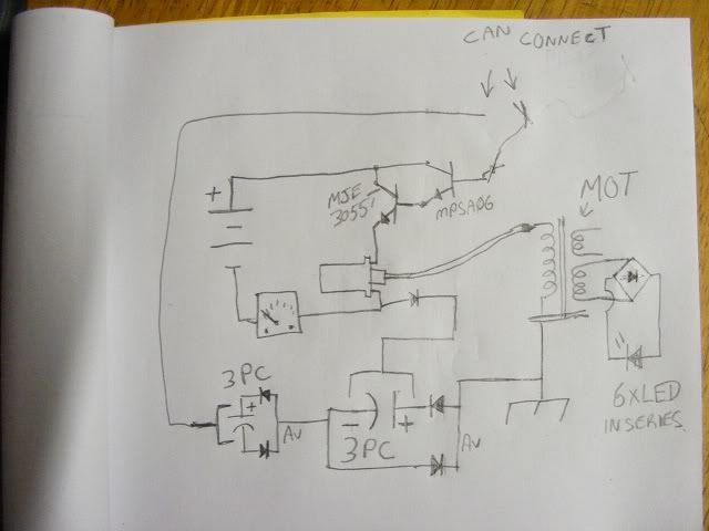
  • Kacher Tesla Circuit with Power MOSFET

    Originally posted by Ganzha View Post
    here is very good schematics for Katcher with Tesla coils

    This image was attached to his post.

    Datasheet on IRFP260N
    Regards,

    VIDBID

    Comment


    • Originally posted by usu View Post
      Hi, vidbid !

      At this part which you got a screen he talks about design of Kapanadze coil.
      Previously, he explained the principle of the hydraulic and mechanical models.
      All of this he compares with the principle of Smiths scheme .
      Also he says that everywhere here is used the same principle.
      I must say it (coil on the screen)reminded me Joule Trief design(ferrite tube resistor).
      It is also the same design that zilano describes in her previos posts.
      But why we have got it all at the same time?
      In my opinion It is very suspicious.


      I would like to see you opinion about this all.

      Best regads,
      Sergey.
      Hello!
      I like what you said! Very suspicious! For sure! Do you think me, Zilano, Dynatron - are one team? I mean super duper agents working for oils magnats?

      Cool!

      I have to buy sun glasses!

      Comment


      • Zilano Harvester

        Originally posted by zilano View Post
        @kdkinen


        zzzz

        @Sergey,

        What do you think?

        Message me if you want your comments private.


        image courtesy Zilano

        Is the image above connected to her description below?

        I'm still trying to figure it out.

        Originally posted by zilano View Post
        individually both are hot but combined this way they become cold meaning radiant.

        and this radiant is capacitered with split copper tube inside ferrite rings and inverted with usual iron cored trafo and we get hot electricity. radiant is captured by one plate of cap shaped in C and there is another c within this big C which is fed to the ferrite rings and we get dc that can be inverted. cold electricity is polarized form and there are otherways too to convert it. Leedskalnin was so right in his concept of helical resonating magnetic currents they are always two. we get hot electricity when they r two and running against each other giving hot electricity. the ferrite make it provide the lacking helical in cold electricity. anyways thats it. we can see individual poles cant do any work we need both. destroying the dipole gives us energy we call it as hot electricity. and thats what we need. yes for generation the dipole must be saved but separated as polarized to reconvert it back again.

        i need to be travelling again got to rush to the airport. cya later another time!

        rgds

        zzzz
        I'm not really sure what the word capacitered means. I googled it but couldn't find a definition. I assume it means that a charge is somehow induced into the split copper tube or pipe.

        Well, some elements of the diagram above look a bit like some of the components in this image:


        Link to Video: FREE ENERGY GENERATOR BY KAPANADZE 100 KW - PART -1 - YouTube

        Link to Vladimir Utkin's book: http://www.free-energy-info.co.uk/VladimirUtkin.pdf See page 25
        Last edited by vidbid; 05-05-2012, 06:55 AM. Reason: Enhancements
        Regards,

        VIDBID

        Comment


        • Originally posted by myenergetic View Post
          [ATTACH]10997[/ATTACH]@ Vidbid

          Wrong
          Sorry about that. My mistake.
          Regards,

          VIDBID

          Comment


          • Idea's.

            Hi all, Last night I experimented with a variation of mr cleans setup, with very
            interesting results.

            This is basically the setup I experimented with, it changed as I went so the
            circuit drawn was at a midway point in my experiment. I ended up with the
            frame and secondary of the MOT connected to the ground wire.

            I noticed the circuit would oscillate without the ground connected to the
            Earth, just a wire was needed.


            Video clip is unlisted because my setup was dangerous. I disassembled the
            circuit because I think I will experiment with some less dangerous coils.
            The cap on the play board is a 1000 uF 50 volt and the two big ones
            connected to ground are 470 uF 400 v each their voltage is shown on the
            analogue V meter on the wooden board.
            Clean oscillator.wmv - YouTube

            I took a quite nasty shock from that circuit after the MOT was grounded
            when I touched the base wire at the time I had a small coil attached to the
            base and was shocked when I put pressure on the base, so the voltage I
            assume was fairly low but it rocked me good. It appears that significant
            voltage and current can be reflected into the "low voltage" portion of the
            setup if it is arranged to allow it.

            The drawing below is the type of setup below I want to experiment with next.
            As yet this is purely concept and is merely a combination of different "building
            Blocks" As can be plainly seen.

            The theory for me is that when the switch is closed and/or the base is first
            "excited" the oscillations start and the base is excited by field effect or noise
            whichever, "placement" might matter. Energy from the ground oscillations
            could be collected into the battery by AV plug.

            The switching should work by the Darlington pair "amplifier" arrangement
            providing a signal to the mosfet gate, a turn off sharpener ties the gate to
            ground. I hope it works but it's just idea for now. I only have larger PNP
            transistors I don't have the MPSA56. I thought I would post it now rather
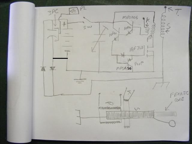
            than later. The mosfet not switching properly is my main concern. The second
            NPN triggered by the MPSA06 is a MJE 3055 so far but it might change,
            I haven't thought about the coils L or C yet. I also considered tying the
            bottom of the primary coil to the bottom of the secondary or just above the
            bottom with a FR diode.

            I will test a MOT to see if the three coils on one of those will work for me, I
            don't like them for experimenting without using extreme caution from now on.
            They're nasty. However I don't expect them to work anyway for a few
            reasons. Oh and electrolytic capacitors can explode if reverse charged in my
            experience ie, wrong polarity.

            EDIT: Oops I forgot to draw a wire between the negative of the electrolytic
            capacitor and the battery negative, there should be a connecting wire there too.

            Colage' circuit.


            Cheers

            EDIT: Corrected PNP transistor part number to MPSA56, I found one, might be
            still ok.

            ..
            Last edited by Farmhand; 05-05-2012, 11:47 AM.

            Comment


            • Originally posted by vidbid View Post
              @Sergey,

              What do you think?

              Message me if you want your comments private.
              Is the image above connected to her description below?

              I'm still trying to figure it out.


              I'm not really sure what the word capacitered means. I googled it but couldn't find a definition. I assume it means that a charge is somehow induced into the split copper tube or pipe.

              Well, some elements of the diagram above look a bit like some of the components in this image:


              Link to Video: FREE ENERGY GENERATOR BY KAPANADZE 100 KW - PART -1 - YouTube

              Link to Vladimir Utkin's book: http://www.free-energy-info.co.uk/VladimirUtkin.pdf See page 25
              Hi,vidbid!

              You are amazing colleague!
              I think you are right.
              This is Turkish 3-phase Kapanadze generator at the picture.
              If we cut off one phase we can make a comparison.
              See the picture in attachment.
              It seems I almost imagine the process of converting.
              Now It's time for the experiments.

              Unfortunately some of details I can't understand .
              In addition zilano doesn't want to answer my questions.

              She looks like a butterfly who is always in the flight.
              I heard that the butterflys use zero point energy
              for flying.( I am not joking)

              Best regards,

              Sergey.
              Attached Files

              Comment


              • Originally posted by Ganzha View Post
                Hello!
                I like what you said! Very suspicious! For sure! Do you think me, Zilano, Dynatron - are one team? I mean super duper agents working for oils magnats?

                Cool!

                I have to buy sun glasses!
                Hi, Ganzha!

                Nice!
                You are really make me fun.
                It seems you are very cheerful person in life.
                Thanks!
                Don't worry about oils magnats.
                Since Tesla days passed they have learned to solve the
                problems quickly ,easily and most importantly cheaply.
                And this is mostly the reason why we haven't got the free energy yet.
                I'm absolutely sure that most of big states already have had
                a source of free energy.
                Russia for example has it 100%.
                Now days it used in spase only.
                This is my opinion.

                I don't want to say here about zilano becouse it can cause a new struggle.
                She has her own the original opinion and this very important.
                They (Z and D) can't be in one team.
                They are just from different galaxies.
                Dynatron doesn't know english at all.
                I very much doubt about that she knows russian.
                If I am wrong it will be fun!
                And we just laugh with you together.

                Also I think they go by different ways.
                Dynatron is the practitioner mostly.
                But zilano is the theorist only.
                Both things are very important for our job . Aren't they?

                I think we have the third one side...
                And this is interested me a lot.

                Please don't take it so close to you heart.
                Because you are cheerful guy!
                We should use this situation for our purposes.

                Best regards,

                Sergey.

                Comment


                • I spent most of yesterday playing with Mr.cleans darlington set up using a 12 volt battery. Mine is consuming considerably more power than what he is showing but it is a very interesting circuit to play with. I am using one wire from a 50 foot extension cord for my virtual ground to the base. I do not have 12 volt lights so I am trying different loads. There is high voltage flying all over the place. I have connected a 12 volt to 120 volt transformer to it and hooked the center input tap to ground and although I can only measure 38 volts it lights a 120 volt led bulb very bright. It also lights a modified flourescent bulb and a 120 volt neon so there must be more voltage there than can be measured. I have used a couple digital meters and one analog and got the same reading. One really interesting thing is that I was able to light a modified flourescent bulb at the opposite end of the 50 foot extension cord with one wire hooked to the base of the transistor, one wire hooked to ground and one wire not used and it didn't seem to matter which two wires that I hooked the bulb to it still lit bright. Recharging my battery now.

                  Comment


                  • Zardox

                    I confirm what you found. I suspect that the wire connected to base of one transistor 2n3055 should be replaced with capacitor somehow because the better capacitance here connected (better metal area) the better output but also the more power drain from battery.It also bites so be careful.
                    I don't have 12V led lights , all I have is single 230V 1W led bulb and I tested it.
                    Very small light output at 40mA with 9V battery but I saw the "squeezing effect" when I touched the case of bulb there was more light.
                    I can confirm also woopy tests with kacher and led lights - it seems the same effect. I can light this led to probably 1/2 of brightness when connected to output car coil using one wire and the other terminal of bulb connected to 20m of copper (insulated) wire. Yet power consumption rised to 100ma.

                    Interesting but not spectacular....

                    Comment


                    • Originally posted by vidbid View Post
                      @Sergey,

                      What do you think?

                      Message me if you want your comments private.


                      image courtesy Zilano

                      Is the image above connected to her description below?

                      I'm still trying to figure it out.


                      I'm not really sure what the word capacitered means. I googled it but couldn't find a definition. I assume it means that a charge is somehow induced into the split copper tube or pipe.

                      Well, some elements of the diagram above look a bit like some of the components in this image:


                      Link to Video: FREE ENERGY GENERATOR BY KAPANADZE 100 KW - PART -1 - YouTube

                      Link to Vladimir Utkin's book: http://www.free-energy-info.co.uk/VladimirUtkin.pdf See page 25
                      Hi Vidbid!

                      I don’t understand the physical constructions of these coils.

                      Left coil:
                      Are the two copper tubes inside the secondary bifilar and the primary is on top of all?

                      Right coil:
                      Is there only one coil inside the ferrite tube or is there a primary coil winded on top, or is that the copper tube on top of the ferrite substitute primary coil?

                      Thank you.
                      Last edited by Garsony; 05-05-2012, 03:09 PM.

                      Comment


                      • It's nothing more than a 1:1 resonant toroidal transformer. I posted testing on these back in 2010 in the kapanadze thread... this was driven with a low power function generator. The last one is a ring oscillator utilizing the A field of the toroid to magnify amperage. The LEDs are all in parallel ( not series ) showing the magnitude of amperage flowing in the final ring. Circuit input to that unit was 12 volts at 30ma - a simple velleman PWM.


                        http://www.energeticforum.com/attach...sformer2.5.jpg

                        http://www.energeticforum.com/attach...ansformer2.jpg

                        http://www.energeticforum.com/attach...ansformer3.jpg

                        http://www.energeticforum.com/attach...scillator2.jpg
                        Last edited by dragon; 05-05-2012, 03:44 PM.

                        Comment


                        • question

                          hi buddy's, someone can help with a doubt?

                          which is the most desirable material to use as the coil core to wind them, of cardboard tube or plastic tube? does the cardboard tube has some negative effects on the katcher circuits? colective hug
                          Light, I Am!

                          You are Not a Body that has a Spirit, You are a Spirit that Has a Body! There is no Path to Peace, Peace is the Path!

                          Comment


                          • Originally posted by TanTric View Post
                            hi buddy's, someone can help with a doubt?

                            which is the most desirable material to use as the coil core to wind them, of cardboard tube or plastic tube? does the cardboard tube has some negative effects on the katcher circuits? colective hug
                            Hi!
                            Use the cardboard tube.
                            Also you can use epoxy for the whole surface.


                            Best regards,

                            Sergey.

                            Comment


                            • thank you uso

                              Thank you Uso... so, i should not wind the coil directly on the surface of the cardboard tube? it must have isolation on the surface?

                              ps: im using insulated thin copper wire for the high resistance secondary coil

                              Originally posted by usu View Post
                              Hi!
                              Use the cardboard tube.
                              Also you can use epoxy for the whole surface.


                              Best regards,

                              Sergey.
                              Last edited by TanTric; 05-05-2012, 04:52 PM.
                              Light, I Am!

                              You are Not a Body that has a Spirit, You are a Spirit that Has a Body! There is no Path to Peace, Peace is the Path!

                              Comment


                              • hello

                                Originally posted by dyatronn View Post
                                Hello!
                                I use online translator
                                The whole secret of Smith in the transformer izrolyatsii.
                                In fact the load on the secondary winding does not affect the inductance of the primary frequency of the LC and, therefore, does not change ..
                                The output transformer should have a large core is 5 times more than the planned output, because the primary winding of the reactive current is the phase shift of the current and voltage by 90 degrees.
                                Iron or metglas magnetic core is a mediator between the primary and secondary. Stores iron core magnetic field, and selects the secondary winding of the power is the core.
                                The transformer at 50-60 Hz on a ferrite core will not work, not enough headroom capacity. In addition, a small ferrite saturation flux density.
                                Here is a picture which shows Smith transformer - this is a big iron core.
                                The configuration of the resonant coil L1/L2 much of a difference does not, the coil may be wound with a one-way, may be an option with the winding CW-CCW-it's not so important, separation of cold electricity is due to the high-frequency, rather than winding configuration.

                                Hello dynatron,
                                Is possible that smith found a way how to solve problems with back emf?
                                do you think he splitted a core into half, to create special transformer?

                                I was also wondering about reactive energy. How he changed a reactive energy into real one? he jus used a capacitors to shif back the phase shift or it is automatic on secondary coil?

                                pls check attached pictures. it is looking that we know a way how to avoid back emf to work agains us.
                                Could you please translate it into english?
                                Attached Files

                                Comment

                                Working...
                                X