 Tweet
Tweet
Nice progress
Hi all again.
@ Soundiceuk.
Thanks a lot our friend for the good info you provided till now here.
Can you please elaborate what you said here :
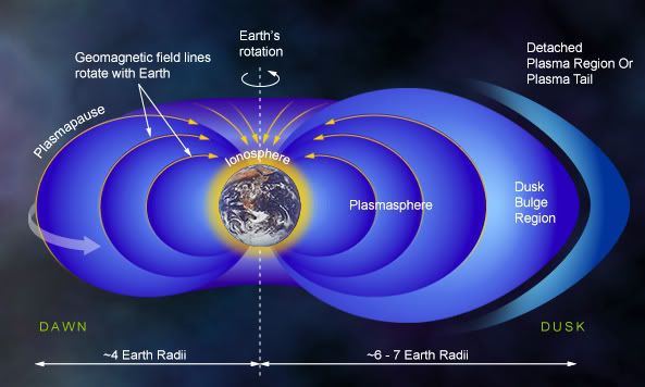
THIS COPIES EXACTLY HOW THE EARTH IS BEHAVING AS A SUPER CAPACITOR SUCKING IN COMIC RAYS!!!! .... ??
coz I`ve stuck on this now.cannot gather the meaning.no inspiration from heavens Thanks in advance !
@ Seeker2011.
Well, as you can read my posts here I am far from being an expert, but to what
you`re asking here, my answer based on Tesla`s experiments around HV HF,
it is better if the spark gap fires as much faster as possible = the better.
Having a so called sharp gradient form in every spark is more desired,which means having
a quenched spark gap as Tesla did.Don even used gas-filled tube for some of his energy machines.

forget the low frequency showed in this picture") it needs to be much higher.
it needs to be much higher.
Moray used the same principle,Gray the same thing,Bedini etc...
Of course your calculated frequency, according to Don himself might come to tens or even
hundreds of KW if properly adjusted yes it is pretty shocking.
I myself have alot work & research to do yet,and my economics are so bad that better not mention it
Anyway, the goal here is to have as much radiant energy manifesting in our circuits for us to have nice results.
Wish you the best at your work-research.
Hi all again.
@ Soundiceuk.
Thanks a lot our friend for the good info you provided till now here.
Can you please elaborate what you said here :
THIS COPIES EXACTLY HOW THE EARTH IS BEHAVING AS A SUPER CAPACITOR SUCKING IN COMIC RAYS!!!! .... ??
coz I`ve stuck on this now.cannot gather the meaning.no inspiration from heavens
Thanks in advance !@ Seeker2011.
Well, as you can read my posts here I am far from being an expert, but to what
you`re asking here, my answer based on Tesla`s experiments around HV HF,
it is better if the spark gap fires as much faster as possible = the better.
Having a so called sharp gradient form in every spark is more desired,which means having
a quenched spark gap as Tesla did.Don even used gas-filled tube for some of his energy machines.
forget the low frequency showed in this picture
it needs to be much higher.Moray used the same principle,Gray the same thing,Bedini etc...
Of course your calculated frequency, according to Don himself might come to tens or even
hundreds of KW if properly adjusted
yes it is pretty shocking.I myself have alot work & research to do yet,and my economics are so bad that better not mention it
Anyway, the goal here is to have as much radiant energy manifesting in our circuits for us to have nice results.
Wish you the best at your work-research.


 you know..
Comment