Announcement

Collapse
No announcement yet.

Donald Smith Devices too good to be true

Collapse
X
 
  • Filter
  • Time
  • Show
Clear All
new posts

  • I had been thinking along a similar lines since watching this video.

    Tesla's Little Secret - YouTube

    Matt Blythe in the video has never actually made the device, just dreamt is up.

    It needs a voltage regulator too, thats where I lean on someone more competant than me.

    I try not to use 100% of my time, it is much more efficient to use 1% of 100 peoples time.

    This is why together we will be sucessful.

    For a while I wanted to buy Tesla Coils, Plans, Parts, Kits and change the circuit to see what happens.

    I now believe that pumping the secondary (which now becomes the primary) with a square wave pulse is possibly the way to go.

    If you look at the circuit diagram:


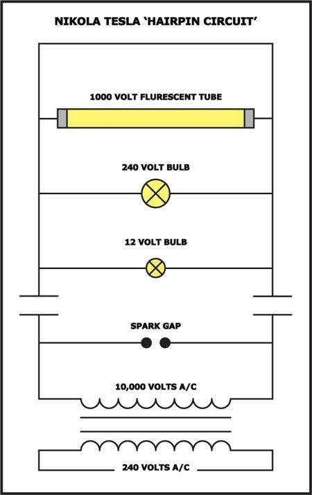
    I believe this circuit is the way to create scalar current and gave Tesla the basis for wireless transmission.

    Comment


    • Originally posted by a.king21 View Post
      The biggest thing I'm concentrating on right now is the output transformer.
      It's been staring us in the face but we all want to make sparks and light lights, forgetting that the Tesla CW/CCW quasi bifilar output coil is the KEY.
      I call it the resonant output transformer based on a reverse Tesla coil
      ratio 1 :4 , STRICT! PERIOD!
      Keep all other coils in any circuit build to a HARMONIC of the output if you can.
      The whole circuit will then RING and you won't know where the sound is coming from.
      Zilano uses the wrong English term Bifilar, but now we understand the meaning.
      Thank you Zilano.
      Thank you Tesla.
      Thank you Don Smith
      A.king21:

      Could you pls post some photos or diagrams?
      It confused me.
      Last edited by ostone; 12-27-2011, 03:59 PM.

      Comment


      • "Magic" of spark gaps

        There are many sources of OU which fortunately can be combined. One of those stakes we can hammer down in the ground is a spark gap. Searching for some confirmations and additional knowledge I found:
        See EueJin Jeong Ph.D Physics - especially after minute 3:30
        He states that if we discharge a capcitor via a spark gap the kinetic enrergy of the moving electrons is higher than the static energy (not electrons! see link below!) stored previously in the capacitor.
        He calculates: at a precondition of 10KV / 5 KHz / 10 nF an surplus of 2.5 KW. (minute 9:16)
        He further states that this energy can be harvested via resonant systems only.

        This is exactly what Tesla found: a discharge out of a capacitor increases the usable energy considerably.
        Regarding the magic of a capcitor: see demonstration of MIT starting with minute 2:00. It is not true that electrons are being stored somewhere on the metal surfaces.

        Summary: spark gaps and resonant systems form a very real building stone for real OU systems. This is true for the hairpin circuit as well :-)

        rgds John
        Experts spend hours a day in order to question their doing while others stopped thinking feeling they were professionals.

        Comment


        • Originally posted by JohnStone View Post
          There are many sources of OU which fortunately can be combined. One of those stakes we can hammer down in the ground is a spark gap. Searching for some confirmations and additional knowledge I found:
          See EueJin Jeong Ph.D Physics - especially after minute 3:30
          He states that if we discharge a capcitor via a spark gap the kinetic enrergy of the moving electrons is higher than the static energy (not electrons! see link below!) stored previously in the capacitor.
          He calculates: at a precondition of 10KV / 5 KHz / 10 nF an surplus of 2.5 KW. (minute 9:16)
          He further states that this energy can be harvested via resonant systems only.

          This is exactly what Tesla found: a discharge out of a capacitor increases the usable energy considerably.
          Regarding the magic of a capcitor: see demonstration of MIT starting with minute 2:00. It is not true that electrons are being stored somewhere on the metal surfaces.

          Summary: spark gaps and resonant systems form a very real building stone for real OU systems. This is true for the hairpin circuit as well :-)

          rgds John
          Hi john:

          In the hairpin circuit, where's the resonant? I remenberd that karl said the capcitors can any size.

          Comment


          • I think resonance may figure scaler wave not transverse wave. May it's the key of failture.

            Comment


            • Resonant output transformer

              The resonant output transformer is part of the circuit. J L Naudin forgot this and used a microwave oven transformer in reverse and ... FAILED!!!
              REMEMBER THIS. The important thing to remember is the wiring ratio 1 to 4. Measure the wire before winding. In this reverse coil;- total secondary should be 4 primary should be 1. (Harmonics should also work, so later we can try 8:1) Number of turns simply increases voltage or amperage and does not really matter in getting OU. But the primary goes inside the secondary.
              Remember to measure the wire FIRST! If using Don Smith input, make sure the input wires ratio 1: 4 and output wire ratios 1:4 are exactly the SAME LENGTH. That way (if you are slightly out, you can avoid using capacitors)if you use wires with clips you can find the resonant points because the circuit will RING like a loudspeaker, only you will not be able to hear exactly where the sound is coming from because it is the WHOLE circuit which is outputting sound. Later you can experiment by EXACTLY doubling the output wire lengths. But the ratio must be maintained 1 : 4. (Later we can try 8:1)
              Or you can use BIG FAT WIRES.
              It is a bit like making a musical instrument.
              If you use clear varnish on the output coil former you increase the Q. In other words you help RESONANCE! RESONANCE, RESONANCE, RESONANCE. HOW MANY MORE TIMES! Think of Tesla's earthquake machine. LOOK IT UP! Do you think he ever forgot the lesson? 2 watts in - BILLIONS OF WATTS OUT!! Repeat:-RESONANCE, RESONANCE, RESONANCE. IS IT CLEAR!!!!
              Nowadays to avoid RESONANCE, bridges have nodes with spheres attached to avoid ...... RESONANCE. Once again RESONANCE RESONANCE RESONANCE on the output transformer. Now forgive me if I don't post for a while cos I'm building RESONANT output transformers according to Tesla's diagram and script.
              Attached Files

              Comment


              • Originally posted by ostone View Post
                Hi john:

                In the hairpin circuit, where's the resonant? I remenberd that karl said the capcitors can any size.
                My notion. It might need corrections.
                - Every coil performs at it's natural resonance frequency when hit by a voltage/current shock. See 10000V AC coil in schematic from soundiceuk.
                - The short circuit loop performs at a resonce frequency too (one loop coil). This is why some sceptics say that this circuit is a understandable high frequency circuit - and don't think any inch further. Nevertheless with this circuit is something special.
                - The high voltage is being performed by the transformer while the shock is being performed by the spark gap. The following oscillations after the shock will be superimposed an the normal high voltage AC signal from the transformer. It seems to be essential to adjust the spark gap in order to fire at a special time slice of the AC frequency.
                - I don't know how to discern the natural frequency (conventional scinence) and the higher scalar resonance (factor PI/2). (see Meyel demonstrations, extra coil from Tesla, Tesla earth resonance ca. 12 Hz vs. Schuhmann freqeunecy ca. 7.8 Hz) This might be a general clue on working or not working replications.
                rgds John
                Experts spend hours a day in order to question their doing while others stopped thinking feeling they were professionals.

                Comment


                • Originally posted by JohnStone View Post
                  There are many sources of OU which fortunately can be combined. One of those stakes we can hammer down in the ground is a spark gap. Searching for some confirmations and additional knowledge I found:
                  See EueJin Jeong Ph.D Physics - especially after minute 3:30
                  He states that if we discharge a capcitor via a spark gap the kinetic enrergy of the moving electrons is higher than the static energy (not electrons! see link below!) stored previously in the capacitor.
                  He calculates: at a precondition of 10KV / 5 KHz / 10 nF an surplus of 2.5 KW. (minute 9:16)
                  He further states that this energy can be harvested via resonant systems only.

                  This is exactly what Tesla found: a discharge out of a capacitor increases the usable energy considerably.
                  Regarding the magic of a capcitor: see demonstration of MIT starting with minute 2:00. It is not true that electrons are being stored somewhere on the metal surfaces.

                  Summary: spark gaps and resonant systems form a very real building stone for real OU systems. This is true for the hairpin circuit as well :-)

                  rgds John
                  Hi John, a very christmas to u, about the mit video, when i saw it, i supposed that it is all about the dielectric, and maybe electrons are pushed on the sides of the dielectric, what do you think.

                  and another thing, remember the plasma tube experiment of don smith, the glass between the 2 plates ( copper and alum ) i think it has a lot to do in our experiments.

                  have a good day.

                  Comment


                  • Originally posted by a.king21 View Post
                    .....
                    The important thing to remember is the wiring ratio 1 to 4. Measure the wire before winding. In this reverse coil;- total secondary should be 4 primary should be ...
                    Hi,
                    regarding length ratio I red different interpretations. I understand from your post: (please confirm or reject!)
                    - The total length of both pairs of secondary should be 4 times the primary

                    Questions:
                    - The length of wire includes leads to terminals, leads to capacitors, diodes?
                    - Is the intended resonance frequency related to the length (i.e. if the secondary is earth connected this might form a lambda/4 dipole.) If not earthed lambda/2 willbe correct. This might be essential if reverse Tesla configuration used.

                    Further notions:
                    - Conforming Utkin the primary should be a short coil while the secondary should be a long coil. They form very different shapes of magnetic fields. (cross section of short = circle, cross section of long = oval) This enables the magnetic fields to be perpendicular to each other. Thus the interaction of secondary current to primary coil will be minimized.

                    rgds John
                    Experts spend hours a day in order to question their doing while others stopped thinking feeling they were professionals.

                    Comment


                    • Originally posted by frankidel View Post
                      Hi John, a very christmas to u, about the mit video, when i saw it, i supposed that it is all about the dielectric, and maybe electrons are pushed on the sides of the dielectric, what do you think.

                      and another thing, remember the plasma tube experiment of don smith, the glass between the 2 plates ( copper and alum ) i think it has a lot to do in our experiments.
                      have a good day.
                      Hi frankidel,
                      I can't answer your questions just now. I try to complete the puzzle - part by part. I gather notions in order to find valid links. And I share them.
                      If I can't procede any more I have to question all I am shure of all what I learned and all I see!

                      The MIT experiment proves that the electrons jamming on capacitor plates - is a child's tale. It confirms what Tesla found that capacitors do special things. Bedini confirms, Zilano confirms. All have their special terminology - but they confirm.
                      Additionally I'm not shure if there is any measurable effect on dielectric material only. I intend to measure next year.

                      I add some notions:
                      Conforming Tom Bearden electrons do not jam along the wires pushed by the battery voltage. By the switch on event they are energized and this is done i.e. by Bedini type short pulses.
                      But if electrons are energized they come out of their car house and drive by themselves like littel motor boats. The electric current is a tired side effect of the real event. As it is a side effect - it can be omitted.(term: open circuits). And this Bedini type energizing seems to be stored in a capacitor being able to produce usable current through resistors - later on at discharge event.
                      This might explain why sometimes a earth connection ist so important - in order to enable the energized electrons (open circuit) to flow and produce normal lossy current.
                      An additional level of complication seems to be that electric event is composed of two symmetrical effects. This is discussed in Utkin paper especially regarding cw/ccw coiling. Magnetically they oppose and delete each other but another energy flow is being added - independent from wind direction.

                      There are some other notions: alignment of the capacitors regarding the coils might be essential. (see Michalsky experiment)

                      As I stated above - these are some notions not being digested in my brain. All are still juggled in order to find a good resting place for reuse.

                      Anyway, I have now a good feeling and allmost all material and metering required in order to start experiments in January. I will share. Thanks for your scharing!!!!!!!!!!!!

                      rgds John
                      Last edited by JohnStone; 12-27-2011, 09:46 PM.
                      Experts spend hours a day in order to question their doing while others stopped thinking feeling they were professionals.

                      Comment


                      • Originally posted by a.king21
                        I'll tell you when I've built it. You can only go so far with theory, then you have to experiment. My gut is stick to the 1:4 ratio in the output coil. .............. There's an AIR BARRIER!! And there's no spark gap at that point! the only link is MAGNETIC RESONANCE! Hail Don Smith if we're right.
                        Thanks for sharing your hints.
                        - You talk of electrons being available. May I add the notion of Tesla who gave the advice to make the copper weight in primary and secondary the same.
                        - Regarding the resonance in NF range. Will you do it by correspnding external capacitors initially? My first test coil (4" diameter / 50 turns / 20" length) performed around 800 KHz at natural frequency.
                        rgds John
                        Last edited by JohnStone; 12-27-2011, 09:42 PM.
                        Experts spend hours a day in order to question their doing while others stopped thinking feeling they were professionals.

                        Comment


                        • If you haven't seen this hairpin circuit video when Alex shunts the hairpin holding the shunt with the scope attached watch:

                          scalar energy device - YouTube

                          fast forward to 2:20

                          My experiments have shown the NST can be replaced with two ignition coils wired in anti parallel removing a large part of the danger element.

                          The spark gap can be replaced and more importantly silenced with a xenon flash bulb from a disposible camera.

                          This circuit needs more experimenting with. The strangest thing about it is that it lights any bulb to full brightness.

                          I don't think too many people have messed around with it because of the mains voltage risks.

                          I wonder what else will run from the scalar current?
                          Motors, radios, computers???

                          What caps would you buy to experiment with if money was not important as I have the driver and ignition coils.

                          Comment


                          • Originally posted by a.king21
                            Additionally attaching a neon to the output acts as a good indicator also.
                            How to attach?

                            Comment


                            • Originally posted by sinergicus View Post
                              Hi .this is a working one THRIVE! (Prospera!) ROsub on Vimeo

                              Do you remember about romerouk ? He started his own forum ...just look at this thread Tesla- Kapanadze generator .You will find few very simple overunity device schematics posted by him , and confirmed by others to be workable ...

                              Here is one selfcharging circuit at page 9 Tesla- Kapanadze generator

                              very similar with zilano schematic given to us at the beginning of this thread ( and unfortunately deleted after a while) ....
                              The waveform on page 10 shows a linear increase. This means the energy is increasing exponentially 2nd power. If the input is constant on each waveform rise... hmmm...lol

                              http://underservice.org/index.php?ac...tach=526;image

                              Comment


                              • neon bulb

                                At high voltages the electric field exists outside the wire (Steinmetz). As a result a standing wave is set up between the neon bulb and any earth or virtual earth. A virtual earth is a bowl of water, a coil of wire or a human body which is mostly water etc. Consequently you do not have to physically attach the neon to anything. Simply holding it near to the output will indicate
                                the strength of the field. Alternatively attaching one wire to the output and the other end to earth ground will light the bulb. This is the best way to check for increasing electrical output. The standing wave is AC. So obviously you can bridge rectify it to charge capacitors. In fact this is the basis of one of Utkin's experiments. He additionally screens the output with a parallel plate capacitor to "blind" the device. I've tried it and it works but it doesn't give me enough output to get excited about. BTW This is the method Tesla used, but of course his coils were the size of a room. Anyway, using this method you can find nodes in your circuitry and obtain power by joining two nodes - as the SAAAR team did in the Lithuania experiments.
                                But remember RESONANCE. We should concentrate on the RESONANT OUTPUT TRANSFORMER. It's probably the main part of the clue, which we have all overlooked. I welcome resonance experiments on output transformers. Keep your eye on the ball.

                                Comment

                                Working...
                                X