 Tweet
Tweet
I'm starting this to begin a conversation about the POTENTIAL of potential difference circuits, and possibly to get folks to look at them in a new way and consider some things they have not considered before. I am posting a beginning video more to PROVOKE some people, and I know I am going to poke the bear with what I say. Whether I believe all of it or am just having fun poking the bear you can determine in time. Regardless, I will be pointing out some things that perhaps you have not considered before and maybe we can begin some explorations together that lead us in the right direction. And as I have already been a long way down this road, I can help avoid some detours and point out some shortcuts. At a minimum, I can keep it headed in the right direction.
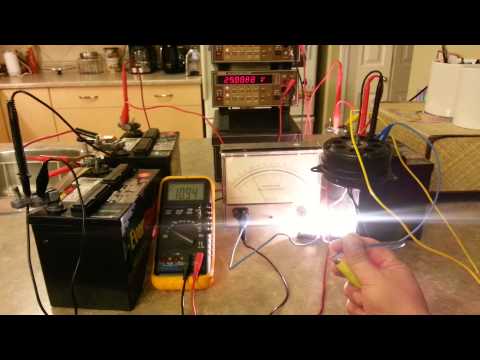
I purposely left "amps" out of the equation in this first video for some specific reasons as I wanted to focus on voltage and what happens in these kinds of circuits that make them difficult to work with. But as you watch the video, amps should be in the back of your mind, because without current flow, or movement from a higher voltage source to a lower (potential difference) electricity doesn't do much good now does it? Case in point: The light bulb in the first part of the video that "sees" no potential difference from one side of it to the other, so even though it is part of the circuit, in SERIES with a load that is running, it doesn't light up.
I posted this particular circuit a LONG TIME back and some people even replicated it and said they saw nothing of value in it. Did they play with it? Did they experiment with different loads and different KINDS of loads? NOPE. And so they learned what they DESERVED to learn. Baby steps people. Let the discussion begin.
https://youtu.be/u_5hpNfJ8Ko

")
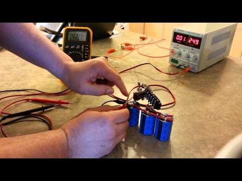
 We have come along way together and I am all set up with what you have recommended folks should buy. For instance efficiency of boost modules and the ones with common grounds or negative terminals that are the same on the input as the output has. They are internally connected on the circuit board. Which I had originally asked you and the other guy but neither knew so I bought one and found this out by looking at the traces on the circuit board.


 .
.
Comment