Announcement

Collapse
No announcement yet.

About Han Coler electricity generator

Collapse
X
 
  • Filter
  • Time
  • Show
Clear All
new posts

  • #61
    amplification bell

    Double tuned amplifier: Adding magnets to the primary would lower Inductance and raise frequency. The resonant twin would need variable capacitance reduced to raise the frequency to its optimal "Q" factor for the loop gain. The two outer caps would be shared by one both power and destination!

    Last edited by Allen Burgess; 10-09-2019, 06:39 PM.

    Comment


    • #62
      RLC resonating circuit.

      The magnet acts as a negative resistor in the RLC equation. All the proportions remain the same. We lack a unit of negative resistance, so I am naming it the "Alph". This is an inverse Ohm and directly proportional to the inverse Henry of inductance.

      The Twin LCM formula places Alphs as inversely proportional to tuner capacitance voltage. Magnet strength has little to do with the effect the magnetism has on the coil inductance. That effect needs a separate value not gauss.

      This is an area of suppressed science. An entire shelf of text books is missing from our science libraries on this subject.
      Last edited by Allen Burgess; 10-10-2019, 02:20 PM.

      Comment


      • #63
        2Sgen looper

        Connecting a fixed value capacitor to JLN's nano perm toroid coil pictured above and a variable capacitor to his inductivly coupled output coil would allow us to tune them as a resonator with a sufficiently high "Q" to generate enough voltage gain to return power to source. Loosening the coupling can regulate the output.


        An SJR3 transistor would run it fine.
        Last edited by Allen Burgess; 10-10-2019, 02:48 PM.

        Comment


        • #64
          Magnet increasing flyback

          Inksel gets the. effect:

          https://www.youtube.com/watch?v=EQJFuKvrUEs

          Comment


          • #65
            Earth resonance

            My "Spiral Toroid" quadfilar coil has been resonating for over six years. Two bifilars of identical inductance. I believe the resonating frequency is driven by the Earth's magnetic field.

            I reasoned that every resonate "Q" value frequency between LC tanks of identical inductances must share the constant frequency of this magnetic resonance of the Planet and be a constant value.

            This apparently creates a strong carrier wave for every high frequency radio broadcast. The magnetic power band is right at the lower edge of the radio frequency.

            All Double tuner "Q" must be the same frequency as Earth's magnetic field resonance. How could it be other wise?
            Last edited by Allen Burgess; 10-15-2019, 12:11 AM.

            Comment


            • #66
              The Earth is a self tuning resonator that works just like our double tuner:

              Last edited by Allen Burgess; 10-15-2019, 12:34 AM.

              Comment


              • #67
                Wadencliff

                Here's Tesla's scaled up version: This resonator tunes top and bottom, the lower capacitance is labeled "G".

                "The coil in CS had a 15 m diameter. Big, but not nearly big enough to get a 12 Hz resonance frequency. That would require a wire length of 300,000,000 / 12 /4 = 6,250,000 meter! He says “a very large self-inductance” and a “comparatively small” capacity. The cupola of Wardenclyffe was a relatively large capacitance but compared to the inductance of the entire planet it was only very small. The coils in CS are in the order of 10-20 mH, in my opinion that is not particularly large".

                That means the 2Sgen double tuner would resonate at the same frequency as Tesla's Wardencliff.

                This means it would broadcast the power to a receiver resonator!

                Gotoluc demonstrates multiple receivers from a Tesla broadcaster with no rise in input!

                Last edited by Allen Burgess; 10-15-2019, 03:23 PM.

                Comment


                • #68
                  Earth resonance

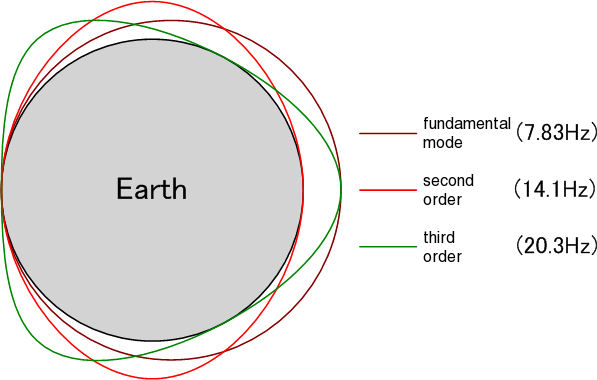
                  The Earth has capacitance in it's crust and induction in it's iron core. The Sun charges the dielectric field. The Van Allen belt is the same plasma that appears in the spark gap of an LC tank. This results in a frequency that triples in the cavities, 7, 14, 21--

                  Double LC tank tuner "Q" is a harmonic multiple of Earth's resonant frequency!

                  Tesla's electric Packard had a vacuum tube resonator that charged the car's battery at Earth resonant frequency harmonic.

                  Tesla didn't have nanoperm and neodymium. The 2Sgen resonator can self loop and power our appliances with Quadfilar receiving antennas with background carrier wave reinforcement from Earth's natural resonance!
                  Last edited by Allen Burgess; 10-15-2019, 11:19 AM.

                  Comment


                  • #69
                    Radio

                    Look at this first radio schematic: There's an LC tank between the coil and Leyden Jars charged by the secondary spark.
                    This signal has very low range due to transmission interference. Both Earth resonance and double tuned "Q" are sympathetic chord frequencies.

                    Two coils and twin sets of Leyden Jars, double tuned to high "Q" would magically generate an Earth resonant frequency harmonic: This broadcasts a Marine quality signal.

                    Tesla's "Magnifying Transmitter" worked on this principle; Tesla's power broadcast band was an Earth resonant harmonic frequency.

                    Our overhead wire conductor grid makes no more sense then the old telegraph lines did for morse code.

                    The 2Sgen resonator will broadcast power wirelessly with no wire connections. The bonus is that we can use the broadcast power equation because at that frequency there is no longer any Ohmic resistance and the range is the radius of a sphere. That means we can recover the power with multiple receivers like Gotoluc demonstrated in his last video:

                    https://www.youtube.com/watch?v=qR1HN0GZ4IQ

                    Luc's test is excellent but slightly inferior because he lacks precisely tuned capacitance and compromises his "Q" standing wave to a beat; Nevertheless, his receiver load has zero effect on the input. The variable capacitor Gotoluc complains about is a worthless radio tuner with large gaps between the conductor plates, not a power trimmer capacitor.
                    Attached Files
                    Last edited by Allen Burgess; 10-15-2019, 01:48 PM.

                    Comment


                    • #70
                      Tesla transmitter

                      Tesla's double tuner patent made "Short wave" radio possible, linking international locations through the ionosphere. Tesla reduces the dual tuner "Q" from 30 MHz in his radio broadcaster to 12 Hz in his power transmitter to harmonize with the Earth resonace.
                      Attached Files
                      Last edited by Allen Burgess; 10-15-2019, 09:29 PM.

                      Comment


                      • #71
                        Dual tuner "Q".

                        Every double tuner "Q" is an Earth resonance harmonic. "Q" is a chord not a note.

                        2Sgen JLN quote: "in this case 200 Hz is the best ratio". We need to tune the "Q" to the pulse frequency. We can connect a Cupola with a trimmer capacitor in series on the secondary output coil and transmit the power wirelessly to receiver resonators tuned to the same frequency..
                        Last edited by Allen Burgess; 10-16-2019, 10:50 AM.

                        Comment


                        • #72
                          Tinsel coil

                          Gotoluc has 4 Tinsel coil videos. His oscillator receiver picks up only one frequency.

                          Tesla's double tuned resonator broaden's the range of frequencies in the broadcast band.

                          This allows the operator to locate the Earth Resonant frequency which is not constant but shifting in a range. We can transmit high amperage at the resonate frequency. How much power can we transmit in the megahertz?

                          There is also amplifier gain in the resonant receiver that fails to appear in the oscillator.
                          Last edited by Allen Burgess; 10-17-2019, 01:46 AM.

                          Comment


                          • #73
                            Tinsel coil

                            Gotoluc's Tinsel coil setup has an output that is directly proportional to the copper mass in the receiver coils.

                            The output is generated in the copper of the individual receiver coils not transmitted from the broadcaster.

                            A series of spiral bifilar receiving coils spaced at the wavelength nodes would transmit and generate power one to the other for any distance like a line of tuning forks.

                            There is no carrier gain in Luc's oscillator. He needs to nest all his receivers around the broadcaster. The resonating receivers would amplify the signal enough to string them out in a line feeding one another serially. The Tinsel coil could be compared to a walk talky while a resonator a CB radio.

                            These coils then create a capacitive pathway for the transmission of power. Dr. Dollard demonstrates the capacitor pathway in his video series. Capacitors store power in voltage across the conductor plates. Raising the voltage on one end of a string of capacitors in resonance will result in a rise in voltage on the other end; Then we can lower the voltage on the far end and sucessfully transfer power that way.

                            The benefit to this Tesla power transmission system is that voltage can be tailored instantly to the load without pumping water up hill from a coal fired generator to feed amperage on demand.
                            Last edited by Allen Burgess; 10-17-2019, 02:30 PM.

                            Comment


                            • #74
                              Self looper

                              Look at the components in this self loop circuit; 321hz d.c pulse square wave, Audio amplifier, spark interrupter and magnets, frequency transformer, capacitor, battery, FWBR:

                              https://www.youtube.com/watch?v=jwJd6KPmWl0

                              The 3rd shumann frequency is 20hz. divided into 321 equals 16. which is 2, 4, 8, 16. The 4th harmonic of the 3rd order shumann frequency.
                              Last edited by Allen Burgess; 10-19-2019, 12:34 AM.

                              Comment


                              • #75
                                Finished version

                                The 2Sgen output coil needs to connect to double tuneing capacitors. The pulsing of the twin capacitors with a second interruption, excites the dielectric field that broadcasts the electric portion of the wave, while the magnetic wave travels through the ground; So the 2Sgen would position under the output coil and a capacitive bell would broadcast the longitudinal wave. This system benefits from a good Earth ground.

                                The capacitors broadcast the electric wave.


                                The electric wave is instantaneous. The magnetic wave is superluminal and travels through the ground, C times Pi over 2. Additional resonant receivers would multiply power. One receiver can charge the power capacitor, and the whole system would run itself!
                                Last edited by Allen Burgess; 10-20-2019, 11:39 AM.

                                Comment

                                Working...
                                X