Announcement

Collapse
No announcement yet.

About Han Coler electricity generator

Collapse
X
 
  • Filter
  • Time
  • Show
Clear All
new posts

  • #46
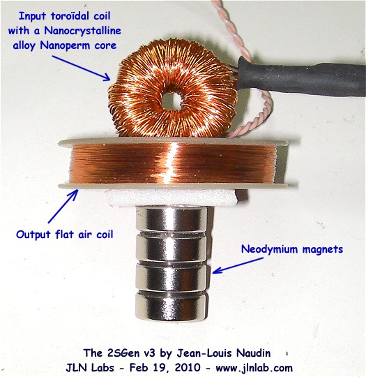
    10 to 20 loop primary and 100 to 200 secondary. The pot core is high in inductance. This is the simple approach Cook used to interrupt his current:

    https://www.youtube.com/watch?v=jO55v3fqiO4

    When high permittivity is saturated by permanent magnets, a negative inductance results in the core!
    Last edited by Allen Burgess; 10-03-2019, 02:24 AM.

    Comment


    • #47
      Demononstration of principle.

      Here's a video demonstrating the principle at work:

      https://www.youtube.com/watch?v=GRnN7DeYHvU

      Comment


      • #48
        Naoki video

        Naoki video:


        Three points; (Not apparent in the video)


        1.-Permanent magnets have zero effect on ordinary current flowing through a wire.


        2.-The amplified flyback current is not traveling directly through the Neo magnet in the Naoki video.


        3.-The amplification lowers input.
        Last edited by Allen Burgess; 10-04-2019, 11:58 AM.

        Comment


        • #49
          Transformer oscillator.

          Simply placing a properly positioned Neo magnet on the secondary lamination of an ordinary 12 to 120 volt transformer, then sparking flyback through it from the primary has the potential to amplify the power over unity!
          Last edited by Allen Burgess; 10-04-2019, 02:04 PM.

          Comment


          • #50
            Jr 3 120vac

            Positioning a neo magnet in just the right adjacency to the secondary of this 120 to 9V transformer with the SJR3 circuit, will amplify the current the same way as Naoki shows in his video:

            https://www.youtube.com/watch?v=pGPDwnYxWps
            Last edited by Allen Burgess; 10-04-2019, 02:09 PM.

            Comment


            • #51
              Self runner

              I believe it is possible to amplify the fly back in a turned around 9v primary by magnet, then feed it into a second transformer and loop the 120 volt output like Gotoluc succeeds at with his self running coil!

              We turn one transformer around and connect the SJR3 circuit. Then we feed the magnified but reduced flyback voltage output from the first transformer into the 9v primary of the second and wire the 120 volt output back into the first through a diode and capacitor.
              Last edited by Allen Burgess; 10-04-2019, 05:03 PM.

              Comment


              • #52
                Transformer magnet

                Here's a question before I upload this "High Water Mark" video. Will simply attaching a strong Neo magnet to a 120 to 9-12 VAC transformer stator amplify flyback spark from the primary to the secondary?

                Does anyone really have any doubt how this test will turn out to work? I can't find any videos that show this effect. What's your guess?

                Would anyone else be willing to help confirm this effect by testing along with me?
                Last edited by Allen Burgess; 10-04-2019, 09:01 PM.

                Comment


                • #53
                  RLC resonating circuit.

                  Look how the transformers are connected and the effect the capacitors have on the voltage boost and ring time:

                  https://www.youtube.com/watch?v=bbpso7zAlvU
                  Last edited by Allen Burgess; 10-05-2019, 12:12 AM.

                  Comment


                  • #54
                    Resonator

                    A 120V DC capacitor could be charged in parallel from a wall rectifier. A 120 volt power transistor wired into a SJR3 circuit and the resonating capacitors between the two transformers would send at least 150 volts AC back to the storage capacitor for rectification during the 22 second ring cycle!

                    The power amplification would come from the magnet attached to the primary flyback pulse transformer.
                    Last edited by Allen Burgess; 10-05-2019, 08:27 PM.

                    Comment


                    • #55
                      Ten year old classic video

                      This is a classic vintage video by Sebosfato:

                      https://www.youtube.com/watch?v=h2PHCqEY55k

                      Comment


                      • #56
                        Additional proof

                        Here again is further certain proof of the effect: Lablanc states at 2:54 that the "Output is greater then the input" after fixing the magnet! Quick math says 5x OU!

                        https://www.youtube.com/watch?v=ni_PdZf5KB4

                        Sebosfato states that the correct magnet polarity reinforces the field collapse. Opposing the rising field has no effect on input!
                        Last edited by Allen Burgess; 10-06-2019, 12:31 AM.

                        Comment


                        • #57
                          Gain

                          Any D.C. pulsed transformer with a sufficiently powerful magnet attached, FACING IN THE RIGHT DIRECTION, will generate an overunity COP!

                          The correct permanent magnet field polarity helps the coil field collapse and amplifies the power of the backspike.
                          Attached Files
                          Last edited by Allen Burgess; 10-06-2019, 07:21 AM.

                          Comment


                          • #58
                            JLN gets a cop of 13.7 with a nanoperm core: The higher the core mu the greater the cop. An LCL resonator tank from twin 2Sgen style coils and capacitors would boost the volatge to compensate for Joule losses.


                            l = ((Vdem^2)/10000) / ((Vmag^2)/10000) = ((35.2^2)/10000) / ((9.5^2)/10000) = 13.7
                            It is interesting to notice that N. Zaev has found a l = 16.3 with a Permalloy 81 NM core
                            Last edited by Allen Burgess; 10-07-2019, 03:10 PM.

                            Comment


                            • #59
                              Here's Lablanc's;
                              Attached Files
                              Last edited by Allen Burgess; 10-08-2019, 04:23 PM.

                              Comment


                              • #60
                                JLN calls for a 2Sgen self looper driver circuit: This can be accomplished by linking two 2Sgen LC tanks, like an ordinary radio circuit, boosting the twin resonating magnet amplifiers' output:


                                The twin transformer resonator in the "Arkiver video" is a commonplace HF radio broadcast signal generator circuit:

                                "The double-tuned circuit, among the most common filters found in radio equipment, consists of two tuned circuits, or resonators, that are coupled together, allowing energy in one to be shared with the other. Designing a double-tuned circuit for use at HF and below is not difficult,'
                                Attached Files
                                Last edited by Allen Burgess; 10-08-2019, 04:23 PM.

                                Comment

                                Working...
                                X