 Tweet
Tweet
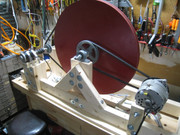
Hi all, Have been working on a flywheel generator, similar to the Chas Campbell device and other similar devices by others.
Powered it up today at 12 volt input, though it is a 24 volt input motor.
It still should have started the flywheel turning at 12 volts, with the permanent magnet alternator in place, though with no load on it.
So the pulley ratio arrangement is not suitable for the small 100 watt scooter drive motor.
Then had to redo the pulley setup and at the moment, still finishing remounting the drive motor in the new position.
Positive, kind and helpful comments welcome.
If you think these types of devices have no merit, then please talk about it in your own thread.
peace love light
Here is a pic of the project at the moment.


Comment