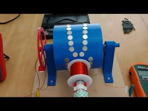
I had a plan, I'd use a makita to drive my test rig. We use makitas for the business so they're available, variable speed
loads of torque and they're pretty much bulletproof. There's one snag which is the braking effect. So the solution to the kinetic energy in the rotor is to use a freewheeling hub.
-
Turion, give us some numbers please like 116pf, 500mH, 660Hz. I realise my numbers are total fiction.
Many thanks.Leave a comment:
-
The means to accuracy with mulifilar winding. Screenshot_20210318-194903_Chrome~2.jpgLeave a comment:
-
I was curious as to how 'real world' measured values would fit into Mr. Lenaerts' equations and charts. Too bad you neglected to record any measurements or remember any. Not all research needs to be done on the bench. Much happens with pen and paper, or, actually, in the mind.Originally posted by Turion View Post
I'm also wondering how your LCR meter separates the inductance and capacitance when you measure your coils. If you find your instrument please show us how you use it.
Thanks,
biLeave a comment:
-
bi,
I haven’t taken those measurements in a really, really long time. I haven’t needed to. I’ve been using basically the same coil over and over on different machines. As of tonight I have no coil that meets the specs of the original coil. All my coils have 12 wires. None of them have been in a machine nor do they have the ends of the wires cleaned of their coating and connected in any kind of pattern. I actually get my new cores tomorrow according to UPS tracking. And I have some black sand for a test core arriving Sunday and am working to put together a permalloy core. So lots of testing to do.
You’re not building anything anyway, and I’d bet you just want that information to try and pick something apart as you usually do.
bi the way, ANY coil can achieve this effect at the correct frequency. It doesn’t have to be a bifilar coil. It’s just EASIER to get there with more strands of wire on the coil. You could simply do it with high rpm and enough magnets on the rotor. As I’ve said like a thousand times.Last edited by Turion; 03-18-2021, 03:27 PM.Leave a comment:
-
Hi Turion,Originally posted by Turion View Post
For your coil that you have supplied the design specs, what are the inductance and capacitance when you measure?
BTW, the book title and author for which you give the link to and copy/pasted a section of its appendix A, Coil Measurements.
Omnidirectional Inductive Powering for Biomedical Implants
By Bert Lenaerts, Robert Puers
I wonder if they used bifilar windings.
Thanks,
bi
Leave a comment:
-
V-gate coil triggered. Add the right circuit to Triger/generate simultaneously, only for those skilled in the art
Leave a comment:
-
An LCR meter will measure L (Inductance) C (Capacitance) and R (Resistance) Sometimes I check Inductance with a function generator, a known resistor and a scope when I can't find my LCR meter. In my shop, in the condition it is in right now, that happens often.
Here is info on self inductance in coils, which is the cause of Lenz, and CAN be engineered around. Also on self resonance. It's too complicated for me, honestly. I am more of a try this and try that kinda researcher. But I keep notes on what what didn't work so that I don't repeat myself TOO often. And I have read about resonance in coils, and why capacitive reactance and inductive reactance CAN cancel each other out.
https://www.google.com/search?client...UTF-8&oe=UTF-8
When the inductive and capacitive reactances are equal, a number of things happen: This condition is known as resonance. Both the inductive and capacitive reactances depend on frequency, with the inductive reactance proportional to frequency and the capacitive reactance inversely proportional to frequency.
https://link.springer.com/content/pd...9075-2%2F1.pdf
A.1.1.1 Self-inductance
Since the self-inductance L is assumed frequency independent, measurement of L can in principle be done at any point in frequency. For an optimal accuracy however, two arguments should be taken into consideration when selecting the measurement frequency ω:
1. The influence of the inter-winding capacitance should be minimal, so ω≪ω0. 2. The impedance Z should be mainly inductive ,hence ω≫ωz.
0
(A.4)
A.1 Single Coil Characterisation 199
A.1.1.2 Self-resonance
Neglecting R in the numerator of (A.2), the impedance Z is real at ω0. The self- resonance frequency f0 = ω0 is hence measured as the frequency where the im-
2π
pedance’s phase crosses zero. From L and ω0, the inter-winding capacitance C of
the equivalent RLC network (Fig. A.1) can be calculated.
For measuring self-resonance, it is imperative that the employed method does not
add parasitic capacitance to the coil and as such affects ω0. The capacitance posed by a coaxial cable for instance will in most practical cases not be negligible against the inter-winding capacitance. It’s influence on the measurement result can hence be substantial.
A.1.1.3 Equivalent Series Resistance
The equivalent series resistance (ESR) R of a coil is dependent on frequency. It is therefore to be measured at the frequency of interest.
The large reactance of a coil compromises an accurate measurement of the small ESR in series. For coils with a high quality factor, it is therefore advisable to cancel out the inductive part of the impedance with a high-quality capacitor. By adding the right amount of capacitance to C in Fig. A.1, a tank is formed that is resonant at the frequency of interest. As stated in Sect. A.1.1.2, the impedance Z of an RLC tank is purely resistive at resonance. The value of Z(s) at s = jω0 is, still neglecting R in the numerator of Eq. (A.2):
ω 02 L 2
Z(jω0)≈ R (A.5)
The series resistance R can be hence be found through measurement of Z(jω0).
Apart from the height, also the exact frequency at which the peak occurs in the
impedance magnitude |Z| is determined by the damping factor ζ = 1 . For a low 2Q
enough ζ, or a high enough Q, the position of the peak approximately coincides with the pole frequency ω0 [156]. The height of the peak in |Z| is in that case given by expression (A.5).Last edited by Turion; 03-18-2021, 12:17 AM.Leave a comment:
-
Turion, what method do you use to measure inductance and capacitance? Thank you.Leave a comment:
-
Update:
My adjustable power supply will be in tomorrow. I have a motor and I have a rotor with magnets and a coil. I am going to put everything together and test several capacitor values to see if there is any speed up under load. That is test 1 if that works I will move on to step 2.
-AltrezLeave a comment:
-
Quantum,
Originally posted by Quantum_well View Post
I am so glad you were able to "gather" that resonance is involved. Here is the quote from my friend the EE for probably the 20th time. I posted it specifically for YOU before. I am posting it specifically for YOU again
It is actually a fact in electrical engineering that any system that uses AC has impedance and the phases of the currents and voltages play a major role. Tesla's coils allow youto have much larger distributed capacitance than winding a normal coil. The advantage of that is that the capacitive reactance and inductive reactance of the coils cancel each other out at a specific frequency without needing to add discrete capacitors. When that situation occurs the magnetic fields of the system cancel each other out and the only losses in a system are ohmic losses. This is what Tesla means by 'no self induction' and this is electrical engineering 101, it is resonance, and the idea that this cannot happen in a motor or generator is not something impossible at all. Engineering the phase of the currents and voltages in a system is done all the time but it is just that the mainstream EE community doesn't investigate it because Lenz's Law is taken.... Well... as a law when in reality it is simply an effect that shows up and doesn't mean it cannot be overcome.
I am making nothing up as I go along. I have given the specs on the rotor I used for YEARS and the coil I used FOR YEARS a dozen times.
The original rotor was 10 1/2 inches with 6 of the 2" by 1/4 inch thick neos. The coil was 3 strands of 1,000 feet of #23. The beginnings of the three wires were connected and the ends of the three wires were connected. There were 12 coils on the machine. The core was iron rods. Speed up under load occurred at 2800 rpm. Anything less and the effect did NOT occur. (A bit later I reduced the length of the wires to 800 feet because the output voltage was 130+ volts and I wanted it closer to "wall voltage", and the REQUIRED RPM went down a bit.)
To try to get the RPM down I went to 6 strands of #23 each 500 feet long. Two strands were put in series. Then two more strands were put in series. Then two more strands were put in series. So I was left with the beginnings of three wires and the ends of three wires. The beginnings were connected together and ends were all connected together. The REQUIRED RPM for speed up under load went down, because connecting wires in series that are wound in parallel INCREASES THE CAPACITANCE.
Then I went to 12 strands of wire. I would put a group of four in series. Then I put another group of four in series. Then another group of four in series. I am left with three beginnings which are all connected and three ends which are all connected. The REQUIRED RPM went down again.
Then I went to a rotor with 12 1"X 3/4"thick magnets on it rather that six of the 2"x 1/4" thick magnets on it. The REQUIRED RPM went down again, and the output of the coils went up.
If you change the number of magnets on the rotor, you change the frequency and everything else must change to match.
If you change the RPM of the rotor you changed the frequency and everything else must change to match.
If you change the diameter of the wire you change the frequency required.
If you change the length of the wire you change the frequency required.
If you change the number of wires wound in parallel that are connected in series, you change the frequency required.
If you change the core material you change the frequency required.
This is the FOURTH time RECENTLY that I have stated that all these variables determine WHAT THE FREQUENCY REQIRED will be. So without knowing WHAT rpm the motor is turning at and HOW MANY magnets are on the rotor there is NO WAY to even get you in the ballpark for having success. Which is WHY I asked for that information and this is the THIRD time I have brought it up. As yet that information has NOT been provided, but your inability to understand is MY fault. PLEASE!
BUT, as I have also said a hundred times, if you had ONLY PAID ATTENTION, ANY COIL will speed up under load using ANY rotor size with ANY number of magnets on it if you have the CORRECT capacitor in parallel with the coil. But because of all of the variables mentioned above, I have NO IDEA what size cap to tell you to use. I have explained ALL of this over and over and over, and it is ridiculous to see you make the statements about me that you just made. It isn't my fault if you are incapable of understanding this stuff.
Why 12 coils? Because I can connect all the strands and have just one long strand. Or I can connect six strands in series and another six strands in series and have two strands in parallel. Or groups of three in series or groups of four in series or groups of two in series. It gives me a LOT of options to try and achieve resonance with the NEW rotor I have which has 22 magnets on it and the NEW core material I am trying. I advised people to wind 12 strand coils because it gives them the MOST OPTIONS with whatever rotor and number of magnets and RPM they will be running at. NOBODY will "replicate" my machine. They will throw together something out of what they have on hand, and I wanted them to have the BEST chance to be successful, so I suggested a 12 wire coil. I always forget about the option to use capacitors.
bi,
There isn't a test you have asked for that I haven't done a dozen times, no data you have asked for that I haven't collected, no measurements you want that I haven't taken. I just haven't shared that data with YOU. And I won't, until after the conference. I've had years and years to do these tests. And I have. Believe it or not, there were MANY, MANY times when I did not get good results for one reason or another. But what I did learn was WHY I failed at those attempts. It's called research. If you had done yours you wouldn't continually whine about MY test results. You would have your own. How's that 7th grade science experiment coming along?
And by the way, I am not changing anything right now to improve performance. I am changing things to have a machine that will not heat up. That's all. Just experimenting with core materials. But while I am looking for a material that won't produce heat why not also choose one that increases, or at least doesn't DECREASE the output.Last edited by Turion; 03-17-2021, 11:56 PM.Leave a comment:
-
You noticed?Originally posted by Quantum_well View Post
And it's always something to put off the big test.
bi
edit:
Designing for high efficiency is great. But. In regards to a machine with 2000Wout / 300Win, what is efficiency? What does it mean?
The definition of efficiency won't change. It is always Wout/Win*100%. So what if you look at power lost?
The 300 watts input per Turion's claim is electric DC from the battery to the motor turning the generator. Assume that motor is 75% efficient. That means the generator uses 225 watts of input power. From tests that we have been allowed to see, including the debunker, that 225 watts is with no electric load connected to the generator coil(s). So I'd guess it could be proportioned as 50 watts to friction and windage due to generator rotor, 50 watts to core loss and 125 watts due to copper loss in coils attributed to resonance of the bifilar winding(s).
So, if choosing a better core material saves all the core loss, how does that affect the generator output? It increases from 2000 watts to 2050 watts. That's a mere 2.5% increase.
2.5% power output isn't all that significant, especially talking about 1700 watts free power. Granted it might be critical in the machine thermal management. But that would have other solutions and ultimately boils down to an economic decision which could be dealt with later.
It is certainly more important to verify, demonstrate, and yes, prove that it actually can perform to Turion's extraordinary claim.
Last edited by bistander; 03-16-2021, 10:45 PM.Leave a comment:
-
Dave has spent thousands of dollars and hours and the whole thing is still up in the air. There must be a reason for using twelve strands and I'd like to learn a bit more about the reason for the taps on the windings.
Resonance is an efficient process but does consume some power and you're basically dabbling with harmonics . I'm only an old farmer and not one of the elite class. The Internet has given me the chance to learn a bit and I must have been 70 when I eventually twigged on to how Einstein's relativity works. The real biggie for me was when I found out how movement translates into inducing a current in a wire and it has to do with relativity. I've had a bad run these last few days and lost my prize mare who was due to have a foal in six weeks time. Yesterday a lovely big calf was delivered dead and to cap it all a lamb was born dead and all it would have neede was a little pull.Leave a comment:
-
Dave has changed nothing of the geometry so you are doing what I knew you would do, nothing. No shame, this is way beyond the average college flunky. You actually have to know how to build something and have real faith. These things escape the masses leaving university who are told they are the elite class.Originally posted by Quantum_well View Post
Leave a comment:
-
I wanted to make a replication and test it myself but what do I make? Turion himself seems to be making things up as he goes so there's no chance of replication.
what I have gathered is he is getting resonance . At resonance, the series impedance of the two elements is at a minimum and the parallel impedance is at maximum. So, with the coils wired as he says the winding has to be very accurate.
From my own experience air cored axial flux generators are less efficient than iron cored generators.Most manufacturers use laminated cores and I'm sure that GOES is going to be a good choice for axial flux.
I'm going to hold on to my tax refund until the situation becomes clearer.
Leave a comment:
Leave a comment: