
-
Hi folks, here is an update.
The engineering company manufacturing my axle and finishing off my rotor didn't get the 17mm reamer for the star washers on time. So the parts will be completed this week.
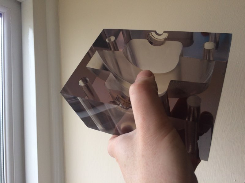
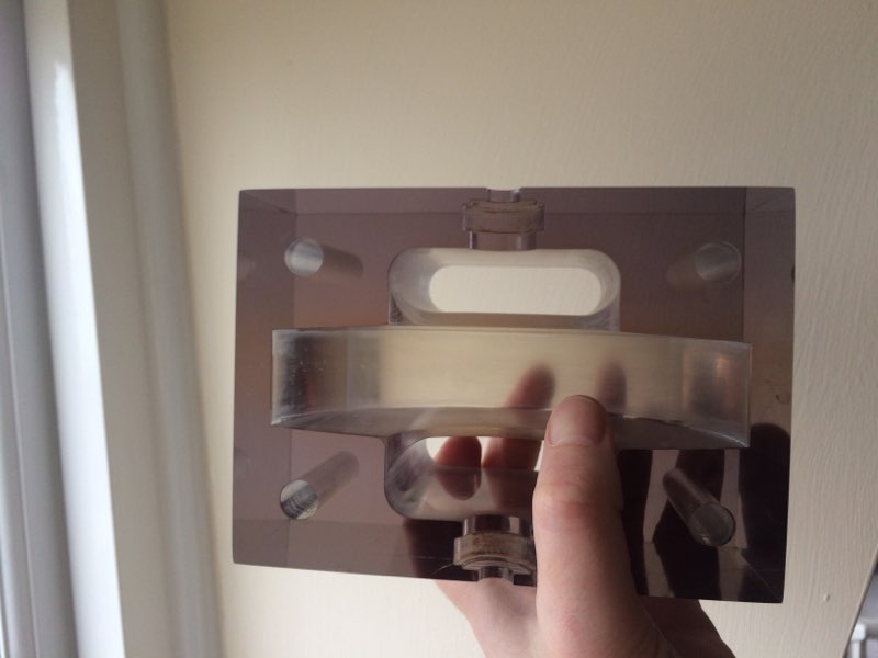
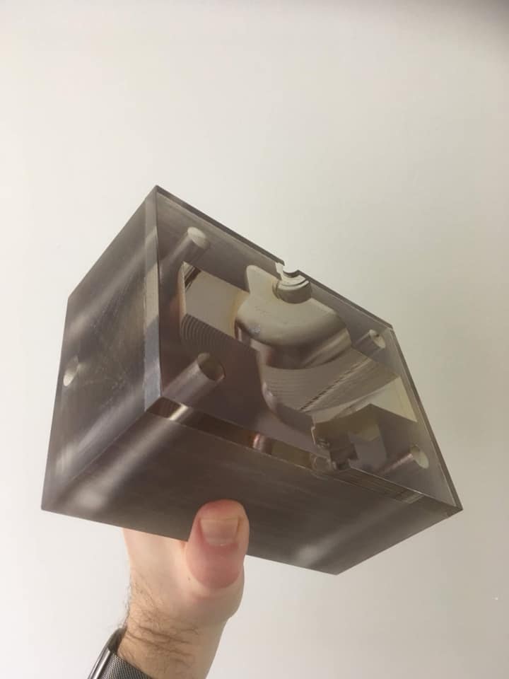
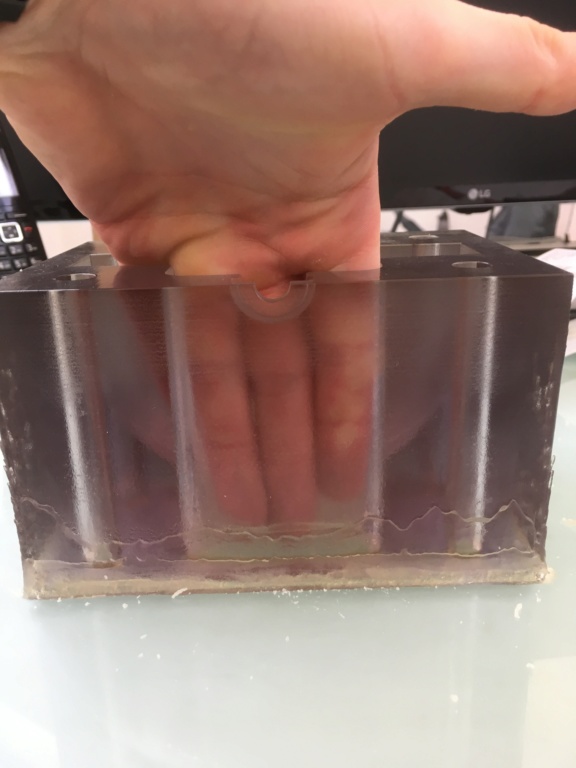
In the meantime I have been sanding and polishing my casing.
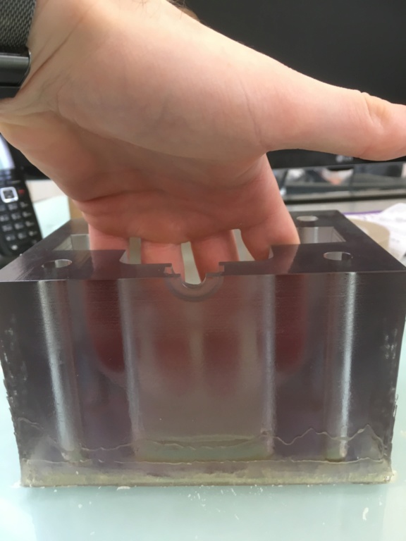
The hard work is paying off. The strange discovery was that the material is like a hologram. You can't see through it on the X axis but you can on the Z axis and also at various angles.
There is still loads of sanding and polishing to do to finish it off.
Here are a few photos of progress.
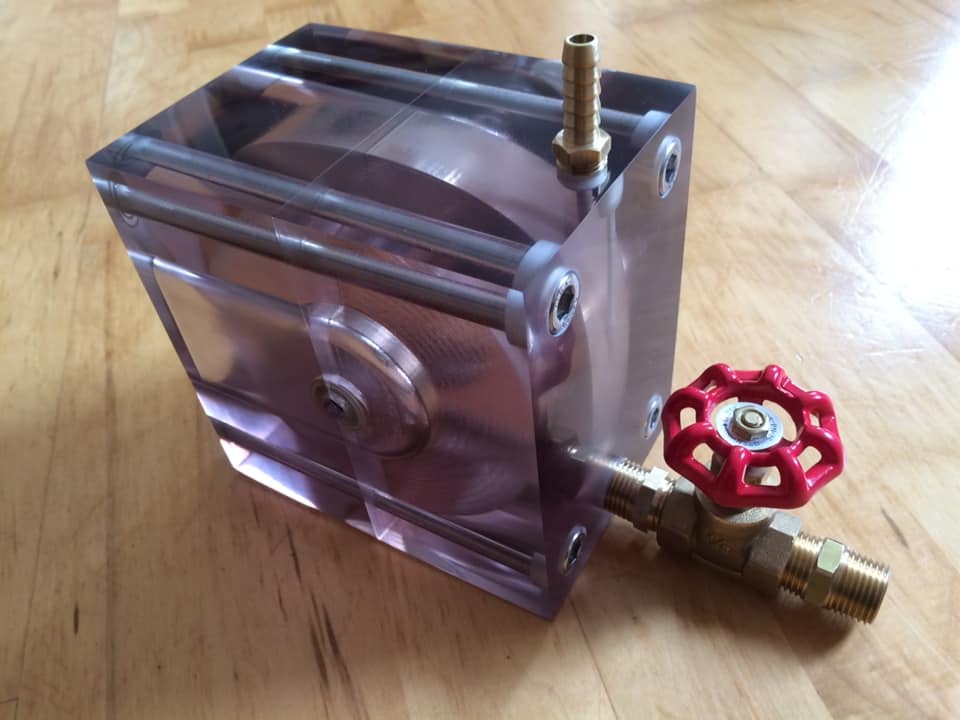
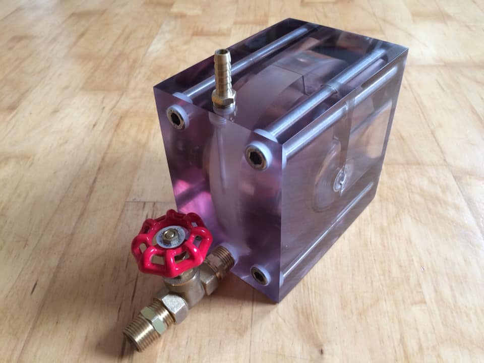
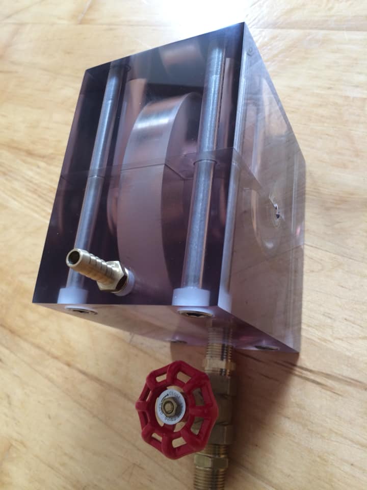


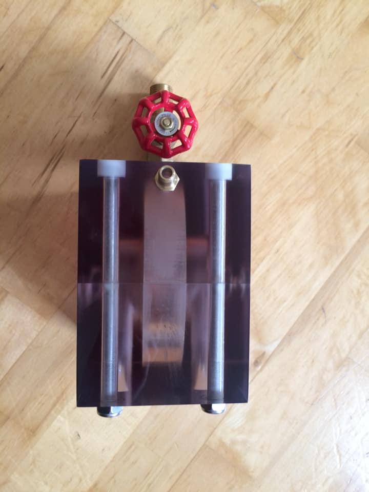
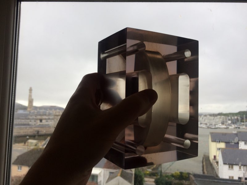
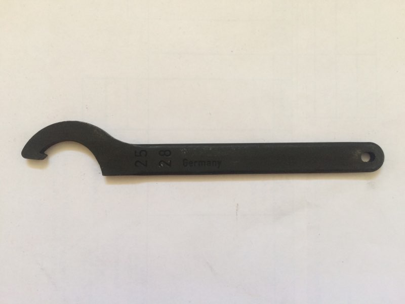
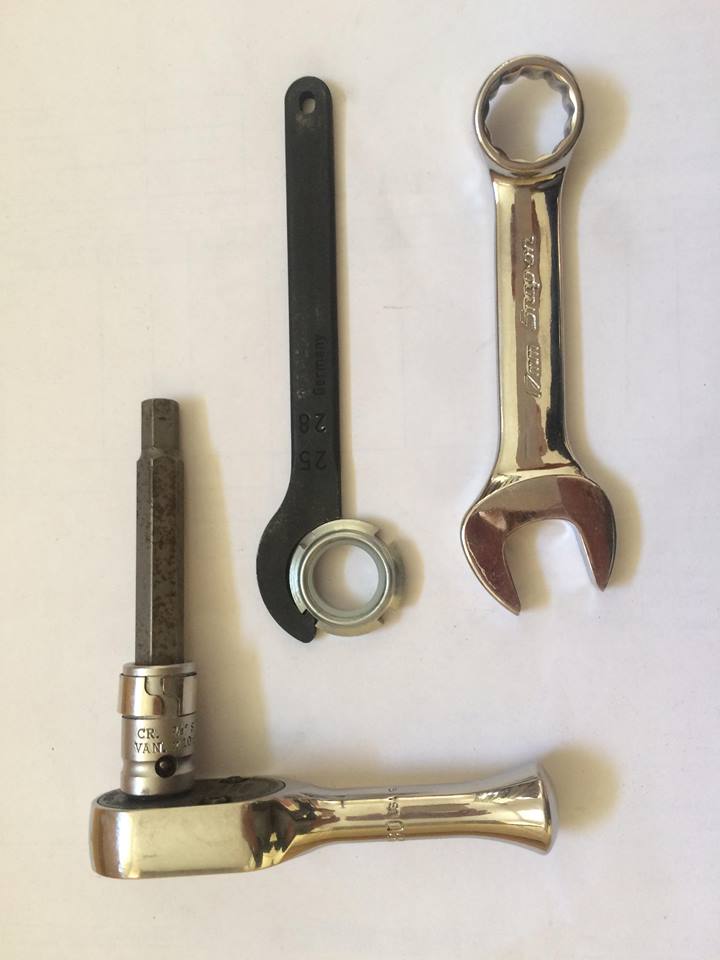
I lay claim to the simplest turbine design that uses the fewest tools for assembly / disassembly.

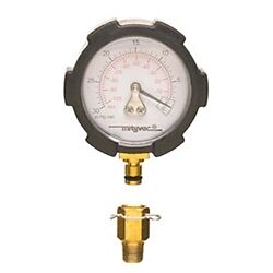
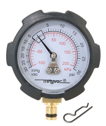
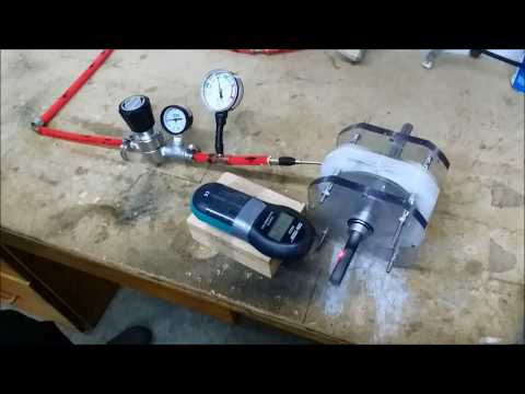
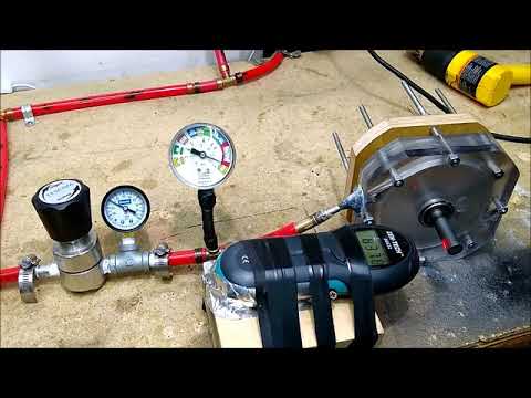
Here are a couple of possible gauge attachments to fit into the port at the top of the casing. One is vacuum and pressure and one is pure vacuum.
I will update my progress in the week.
Word from Idaho is he has rebuilt the Tesla Turbo that made its first appearance at New Years Eve. It briefly showed itself as a holy grail machine and because he glued the rotor to shaft it went into a polycarbonate meltdown because the rotor made contact with the casing.
We chatted on messenger this morning and he told me he put hot humid air into the turbine and snow came out of the twin pump exhausts!
Leave a comment:
-
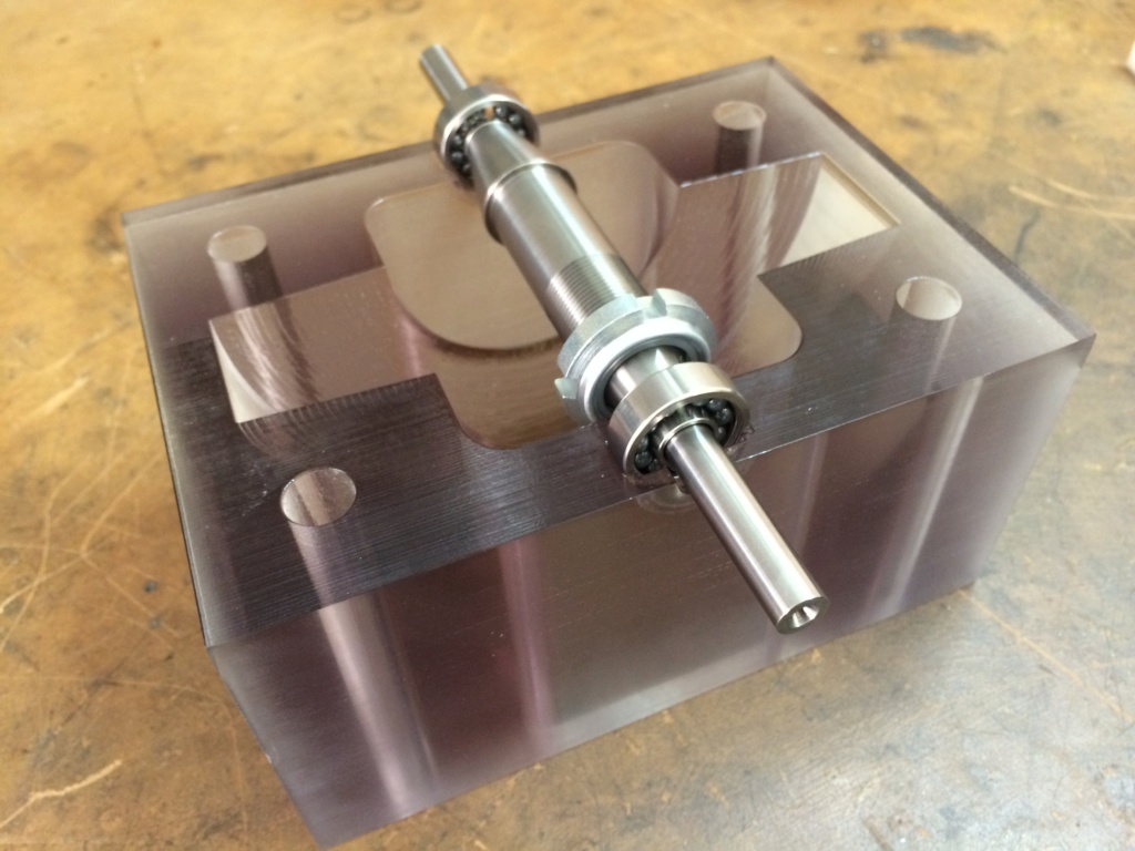
Grade 5 titanium axle without key ways.
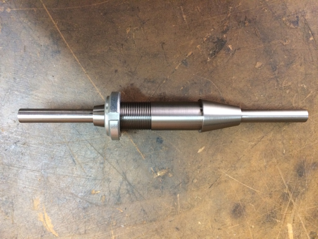
Key ways are being cut tomorrow.
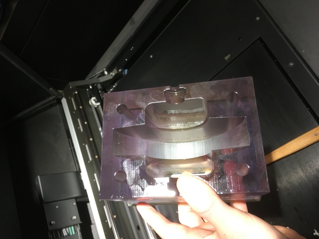
Axle and bearings in exhaust section of casing. Looking from above down the exhaust ports.
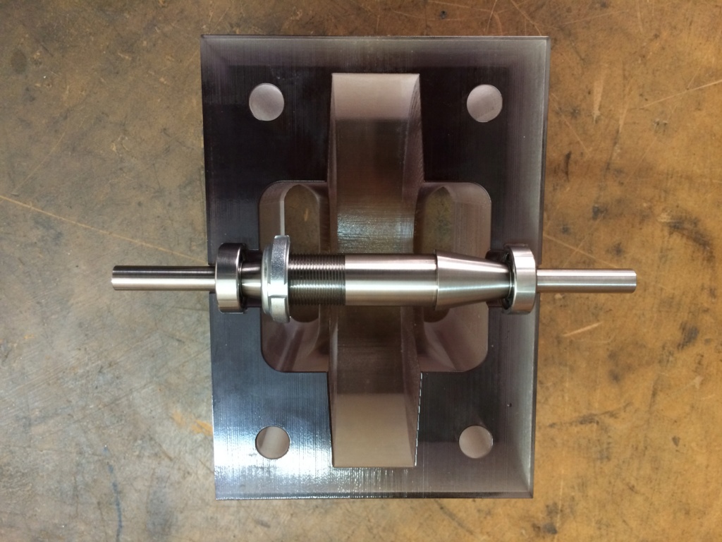
Exhaust section of casing. In my effects to eventually make the casing completely transparent, I've hand sanded this face with 600, 1000 & 2000 grit so far.
Yesterday I received some 3000, 5000 & 7000 grit sandpaper.
The next step will be plastic polish.
I would like to get all the faces lapped and also the rotor discs but I've run out of money.
I've got just enough to pay for the rotor, washers and shaft to be finished.
I'm aiming to for a full disclosure for 4th March which is my 39th birthday!
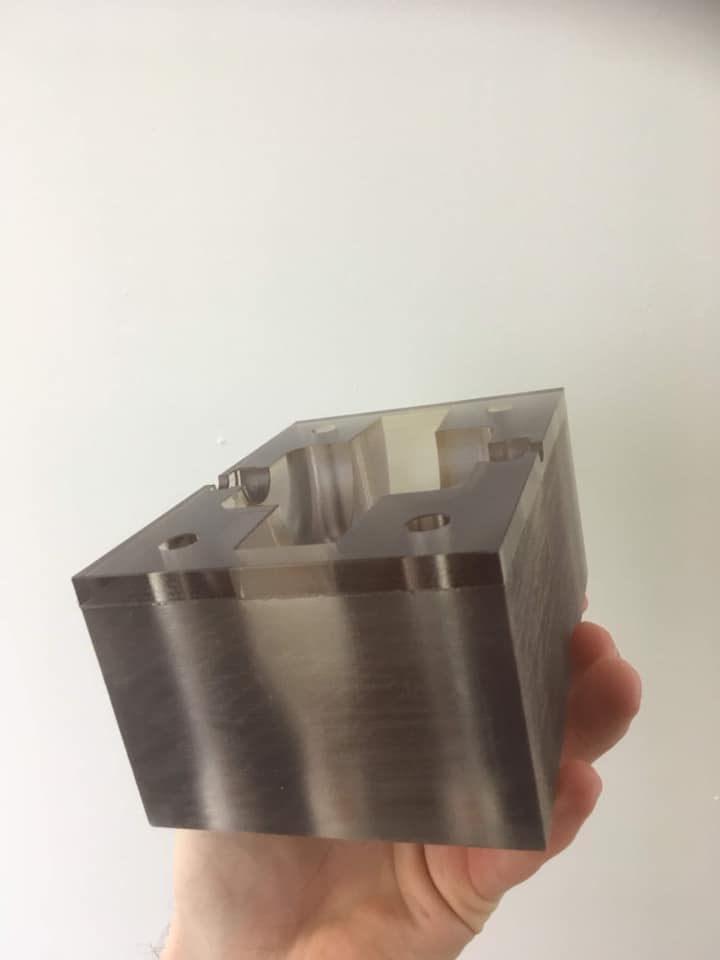
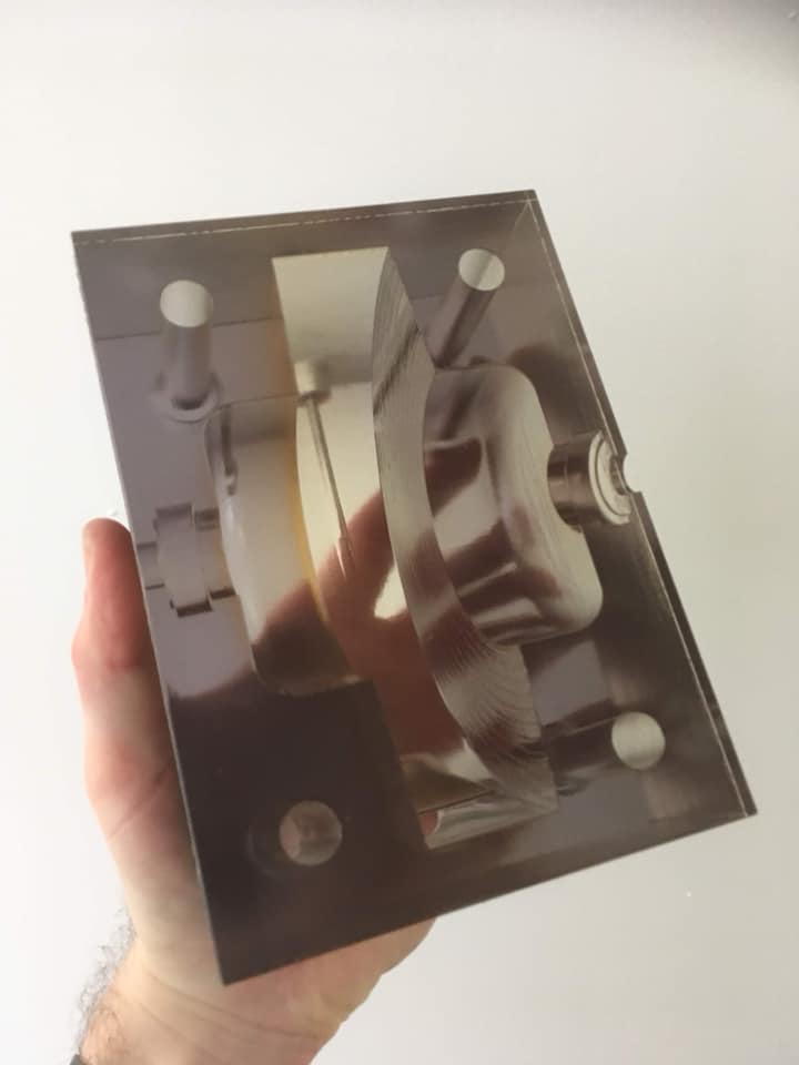
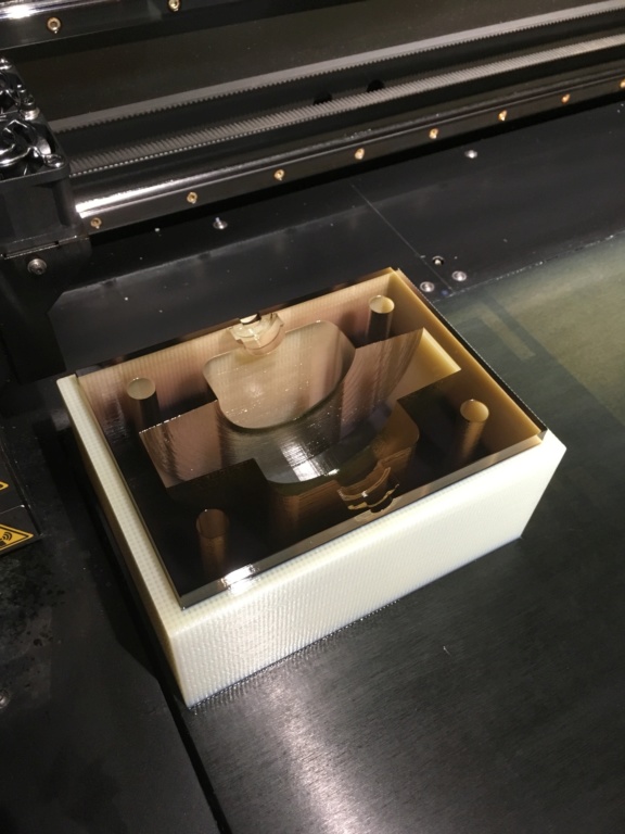
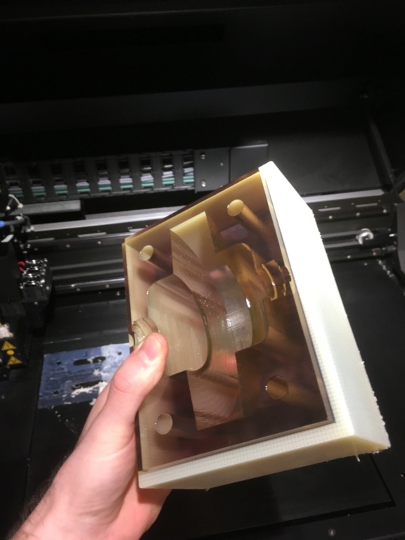
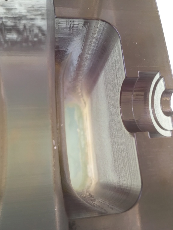
Here are some shots the 3D printer sent me of the inlet section of the casing.
Leave a comment:
-
Hi guys, I’ve had the axle manufactured.
They are adding the key way on Monday but let me have it to do some experiments over the weekend.
The second half of casing is also done. It will be delivered today. I’ll get some pictures posted soon.
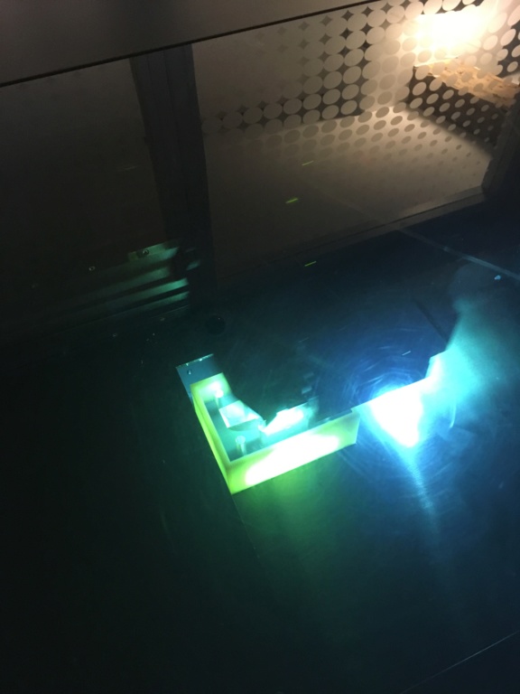
Here is a teaser:

I could have gone much faster but the reflective strip flew off. Was also worried about the axle escaping. Last edited by soundiceuk; 01-27-2020, 11:40 AM.
Leave a comment:
-
I have just received these photos from the 3D printing company.
They have serviced their 200k machine and got it to print properly.
I'm really happy about that!
I will show the other half of the casing when it is done.Leave a comment:
-
Yes, you are right Cadman and I came to that conclusion myself within the last few days.
This is why the boundary layer and impact compliment each other. Discs and star washers.
Here is the first attempt at printing the one of the sides of the casing on a Ł200,000 polyjet 3D printer.
It went a bit wrong according to the 3D printing company!
They left the file on print over the weekend for 20 hours and something happened to the print. So I get this part for free even though it may be salvageable.
They are going to have a second go after servicing the printer tomorrow.
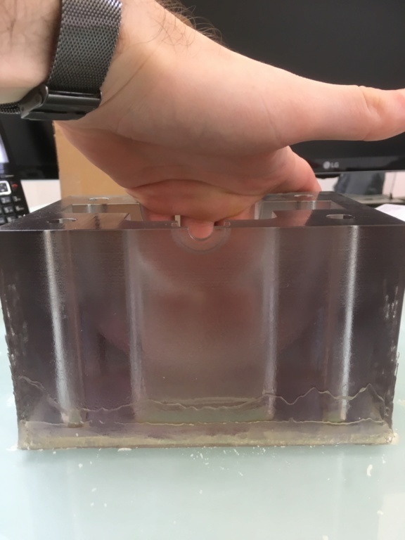
Here are some pics. I think the part can still work.
I've had some amazing prices for having 50 of these made . Around $220 US dollars for both transparent sides of the casing. Which is a steal compared to the cost of one which is around $3000.
I can get the axles done in grade 5 titanium @ Ł60 UK pounds each if there are 50 orders or stainless 316 @ Ł50 UK pounds.
I can do 50 x stainless 316 standard Mk2 rotors for Ł350 each
or
I can get 50 blueprinted stainless 420 bullet proof Mk2 rotors made for Ł700 each. An exact 5" copy of the British 186,082 patent but without the studs. I worked out the studs are for much bigger diameter discs.
Has anyone realised that the previous post by me was the educational proof I needed to realise that air bearings made with just an air gap around the axle and no ball bearings maybe enough to support the weight of the rotor completely after an initial turn because of the vacuum?
With air bearings the top speed goes up dramatically and also the noise level goes down as the ball bearings are not silent.Last edited by soundiceuk; 02-19-2019, 09:37 PM.Leave a comment:
-
Hi soundiceuk. I'm still here, following along with an open mind.
Thank you for the .stl and Solidworks files. I can't see the Solidworks files (yet), I only have AutoCad 2000i. I think there is a viewer available for Windows though.
Ok, now I'm beginning to see how this might function by recovering the latent heat of evaporation in the turbine itself.
Something I just read in one of the Tesla interviews, “The undeniable fact is that the machine does operate, both expansively and impulsively.”
This strikes me as an important statement when viewed in the context of a turbine and compressor combination.Leave a comment:
-
A tight fitting balanced rotor is critical to success!
VACUUM IS THE KEY!
 Last edited by soundiceuk; 01-27-2020, 11:38 AM.
Leave a comment:
-
HEAT ENGINES (BEING THE NEW EDITION OF "STEAM") 1913 By William Ripper, D.Eng. (Sheffield), Hon. D.SC.Eng. (Bristol)
"Where the pressure inside the turbine is less than that of the atmosphere, air tends to leak into the turbine and reduce the vacuum"
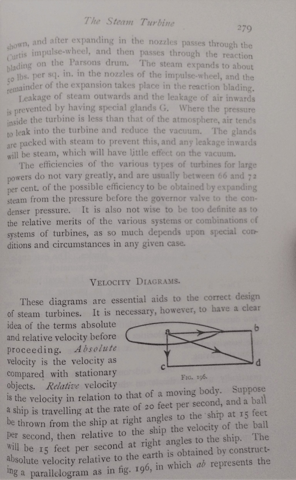
Well in Nikola Tesla's case it has to spiral down the plug hole and create even more vacuum! Last edited by soundiceuk; 02-18-2019, 10:26 PM.
Leave a comment:
-
Here are the builder in Idaho's last two videos. The machine features two discs and one 8 bladed washer in the motor and two discs and a 3 bladed washer in the vacuum pump.
None of the discs are tapered and the gaps are not very tight in the casing.
It is also not using a diverging nozzle. It has a straight port.
 Last edited by soundiceuk; 01-27-2020, 11:37 AM.
Leave a comment:
-
HEAT ENGINES (BEING A NEW EDITION OF "STEAM") 1913

I watched this video and decided to buy the book to see if I could learn anything else.
I accidentally got the 1913 book instead of the 1909 book. However, it still had the information in the video above.
What I did find interesting is this fact.
The combustion engine replaced the "steam engine".
The steam engine replaced the "atmospheric engine".

So Nikola Tesla went back to basics and made the new version of the "atmospheric engine". Last edited by soundiceuk; 01-27-2020, 11:37 AM.
Leave a comment:
-
NIKOLA TESLA'S HIGH SPEED TURBINE DRIVEN DYNAMO
"But the merits of this lighting outfit do not rest on the turbine alone. The dynamo associated with the same is perhaps equally noteworthy by its simplicity of construction, high efficiency and rare and valuable properties it possesses. It consists of a smooth cylindrical body mounted on the turbine shaft and arranged to rotate within a magnetic field of novel forma. There is no brush or sliding contact whatever, the current being taken from stationary terminals to which the ends of the generating coils are connected. By employing the best materials and workmanship and resorting to artifices of design, a most economical electrical generator is produced, the efficiency being over 90% even in machines of very small size having rotors of not more than 2 1/2" in diameter. This generator possesses extraordinary qualities, especially desirable in electric lighting. It is capable of furnishing a current constant within a minute fraction of 1% through a very wide range of speed variation, and as such is ideally suited for running arc lamps or kindred electrical devices in series. More surprising still and also of greater commercial import is its capability of maintaining a constant potential. Such results as are obtainable with it are wholly impossible with other types of electrical generators. It has been found in practice that all lamps but one can be turned off suddenly without the slightest perceptible flicker and even without any observable effect on the needle of a delicate instrument indicating the voltage.
That an apparatus of such simplicity and presenting so many salient advantages should find an extensive use in electric lighting might be naturally expected, but its overwhelming superiority will be better appreciated when it is stated that it occupies hardly more than one-tenth of the space of apparatus of the usual forms and weighs less in proportion. A machine capable of developing 1-kilowatt, for instance, goes into a space of 8 x 8 x 10" and weighs but 40 pounds. It takes not more than one-third of the steam consumed in other turbo-generators of that size.
The guiding idea in the development of this new machine was to evolve a mechanism approximating a static transformer of energy in simplicity, efficiency and reliability of operation. Every detail has been worked out with this object in view. There is no exciter, no commutator, brush or sliding contact whatever, no centrifugal regulator, voltage controller or any such complicated and hazardous device. The machine consists of but a stationary solid frame and two smooth cylindrical steel bodies mounted on a strong shaft arranged to rotate in bearings virtually frictionless. No oiling is required, although a small quantity of lubricant is provided rather as a precaution than necessity. A perfect dynamic balance is secured in a novel manner and insures a steady and quiet running without tremor and vibration. The whole apparatus can be boxed up and depended upon to operate uninterruptedly through long periods of time. The outfit can be constructed in various sizes up to 100-kilowatt or more, and should meet more satisfactorily than any yet devised the varied requirements of electric lighting on railroads, boats, in public buildings, factories and mines, and may also be advantageously utilized in connection with existing plants for replacing belt driven dynamos and storage batteries, and relieving larger engines through the night and hours of small load."Leave a comment:
-
"This is the greatest of my inventions," Tesla went on with great enthusiasm. "Now take my 'rotating field', do you know my rotating field, are you familiar at all with electricity? There are millions invested in it already. Well, that is a very useful thing, but the field is limited to dynamos and motors. But here you have a new power for pumps, steam engines, gasoline motors, for automobiles, for airships, for many other uses, and all so simple."
"But is it really true that you have produced 110 horsepower from a wheel only 9 3/4 inches in diameter and two inches wide, as has been reported?" asked the interviewer incredulously.
"Oh, yes!" was the reply. "And more. We could get more power. We had 125 pounds steam pressure and no vacuum. We ran it that way for hours."
"Was it sustained power?"
"Yes, sustained power. And we could only use part of the drop in pressure; we would have twisted off the shaft, it was so light, if we had been able to use all the energy of the steam. I had to put in a smaller nozzle on that account."
I'm in the same boat with my turbine design. I've calculated that a rotor weighing 1500 grams with a 127mm diameter, spinning at 156,000rpm will have more than 500 horsepower stored in inertia.
The axle I'm having manufactured starts off life as a 20mm grade 5 titanium bar.
The axle parts that stick out of the bearings are only 8mm.
I've no idea how much load this can take.
I'm not really looking to run loads off the shaft long term.
It would be interesting trying to build the dynamo Tesla describes on page 1 of this thread.
I'm all ears for ideas on that, especially as my speciality is more mechanical than electrical.Last edited by soundiceuk; 01-27-2020, 11:47 AM.Leave a comment:
-
Hi folks! I'm going to write a bit about the British Patent 179,043.
Until I understood the fountain patent it was my favourite Tesla patent.
It is responsible for opening up my eyes to the possibilities of what the Tesla turbine can do when built correctly with a tight fitting rotor and bearings that are capable of ultra high speeds over 100,000rpm.
Tesla must have understood that repetition is key to teaching because he repeats himself a lot in the turbine and related patents. On some subjects more than three times per patent.
I've highlighted the parts that I think are most important in this patent.
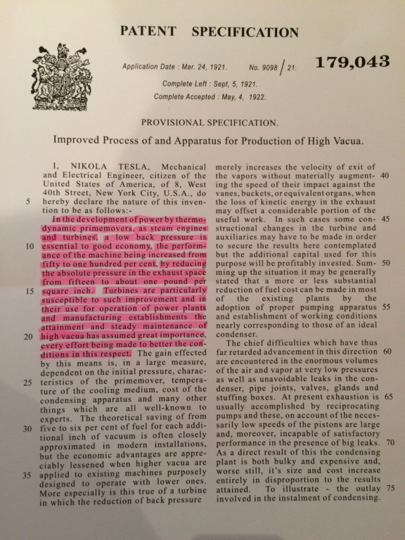
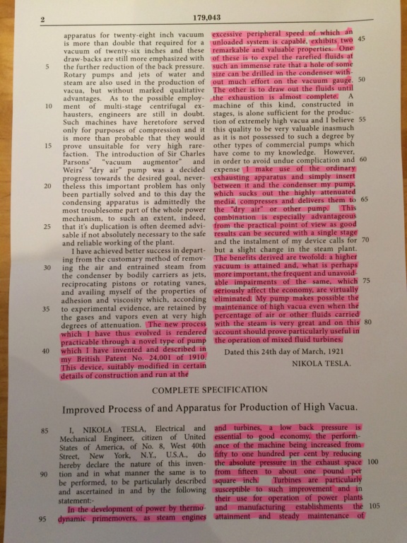
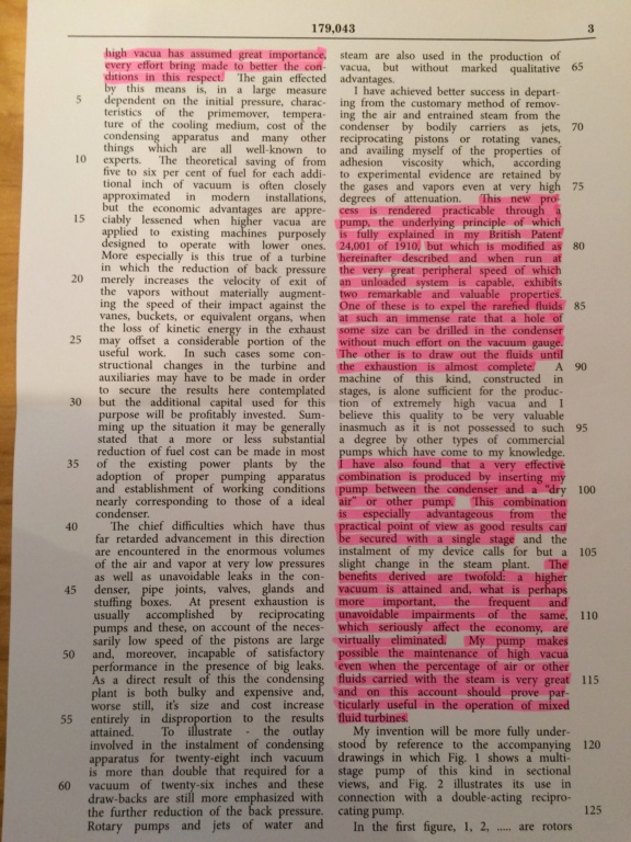
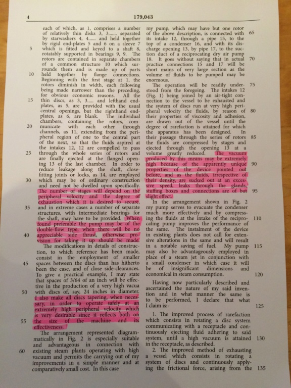
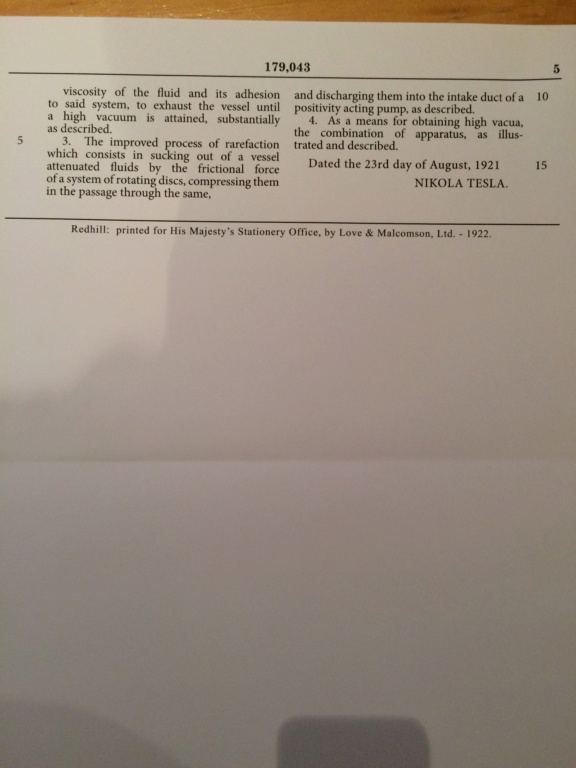
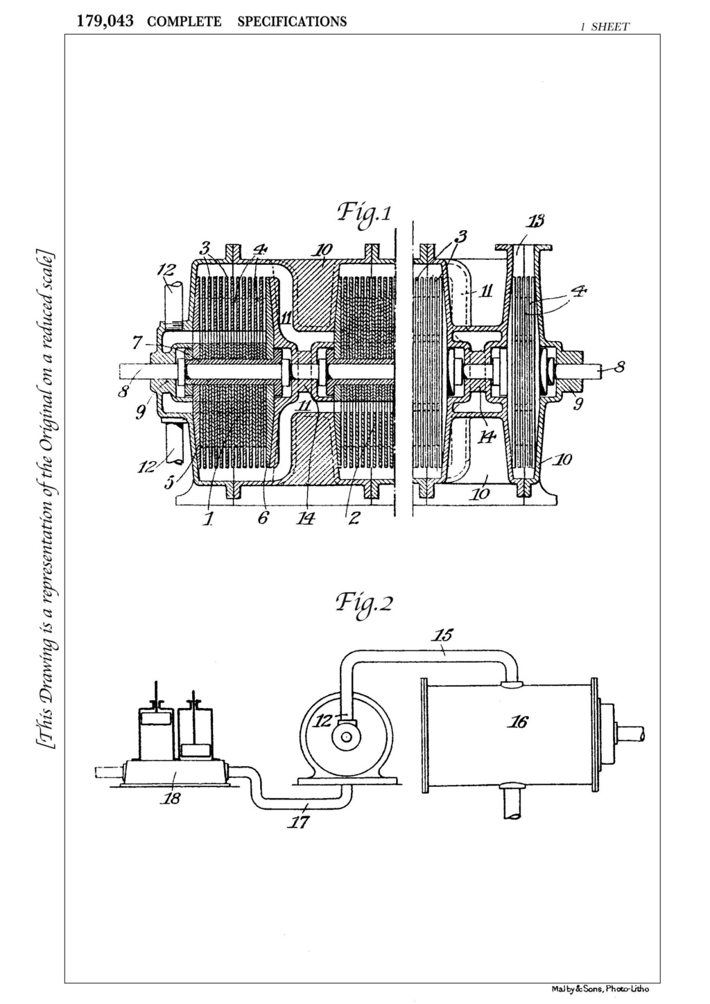
Here is the cleaned up version of the British Patent 179,043 "Improved Process of and Apparatus for Production of High Vacua"
https://www.dropbox.com/s/ezqztmbah3...79043.pdf?dl=0
There are some important things I've noticed within this patent.
1. Tesla states adding a vacuum to a turbine will increase efficiency from 50% to 100%.
2. He claims this is the evolution of his pump from previous British Patent 24,001. This is the same patent as US Patents 1,061,142 & 1,061,206
3. Tesla claims that by having this vacuum pump fitted, a hole of considerable size can be drilled in the condenser.
THE TURBINE IS THE CONDENSER!!!
4. Tesla claims that having a low back pressure is essential to high economy.
5. Tesla claims the vacuum pump works best inserted between the turbine and other pump. I believe he is referring to the 1,061,142 patent or fountain patent.Last edited by soundiceuk; 02-17-2019, 08:47 PM.Leave a comment:
-
I think there are many designs of rotor that will work.
The tear shaped rotor is a definite. Tesla Mk2 rotor is another candidate.
Not only will is pump the fluid, it will also increase the power of the vacuum. Now looking at the YouTube video of the collapsing railway tanker we all know that inches of mercury count.
The larger the pressure difference between atmospheric the more economic the machine.
If 1/25 horsepower does that many gallons per minute. Imagine the lift the design I present will have when it can store over 500hp worth of inertia.
Drawing a few horsepower should be like a fly trying to stop a train!!Leave a comment:
Leave a comment: