Announcement

Collapse
No announcement yet.

Rick's Overbalanced Water Wheel Concept

Collapse
X
 
  • Filter
  • Time
  • Show
Clear All
new posts

  • #46
    We have had zero degree mornings here for 4 days now, and 3 of those days the temperature never went above 20. This afternoon the temperature rose to a balmy 30 degrees. This seems more like January weather than November weather. We also had some snow earlier in the week. It would be nice if we could get a little global warming coming our way, but I don't expect that to happen. Farmer's Almanac says we're in for a hard winter, and they are right about 80% of the time.

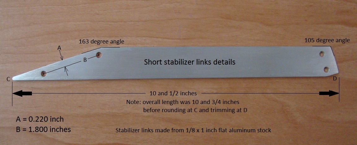
    I have been working on the stabilizer links, and have completed the two longer ones. Here's a photo showing the details for these links.


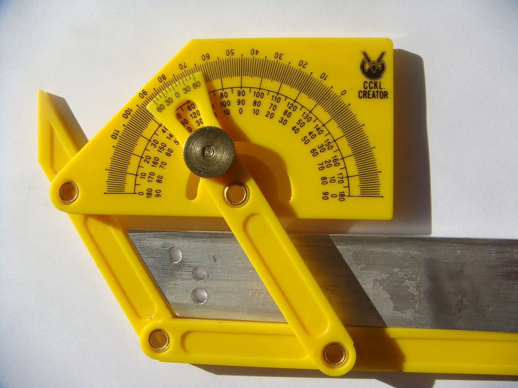
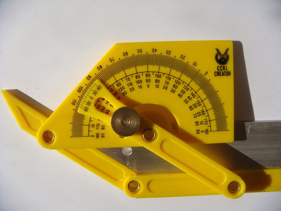
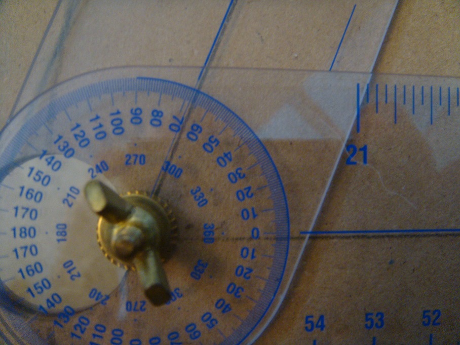
    After attaching one of the uprights to its footing anchor, I placed the 16 inch side of a carpenter's square upon the base, and moved the 24 inch side up against the upright to position it perfectly vertical, and tightened the #10-24 x 5/8 attachment screw and nut to maintain that position. Having already cut the 1/8 x 1 inch flat aluminum stock to the correct length and angles for attachment, I held the stabilizer link in the desired position and then poked a black sharpie marker pen through the holes in the link anchor, and the existing mid-point hole in the upright, to mark the link for its hole locations. I then carefully center-punched the markings using a hammer and awl, and drilled the holes using my benchtop drill press and a 3/16 inch drill bit. The holes may look a bit rough in the photo, and that is because I took the photo before slightly chamfering the hole edges. You will notice that there is an extra hole at the anchor end of the link shown in the below photo, and that's because I used a piece of stock which I had already drilled for use with another fixture. Both links also have a hole near their mid-points, but I "photo-shopped" the above link photo to remove the extra holes so that I wouldn't be confusing anyone. The below photos show the angle details for both ends of the long links. The anchor end of the link is cut at a 123 degree angle, while the upright attachment end is cut at a 146 degree angle.


    Last edited by rickoff; 12-04-2019, 04:57 PM.
    "Seek wisdom by keeping an open mind to alternative realities, questioning authority, and searching for truth. Only then, when you see or hear something that has 'the ring of truth' to it, will it be as if a veil has been lifted, and suddenly you will begin to hear and see far more clearly than ever before." - Rickoff

    Comment


    • #47
      I worked on preparing the short stabilizer links today, and those are now completed. The details are shown in the photo found below. As with the long stabilizer links, there were a couple of holes already in the two pieces of stock that I used, so I "photoshopped" those holes so as to hide them for the purpose of not confusing any viewers. The photo below shows precisely how the link should be made.


      Note that the 10 and 1/2 inch dimension is the the overall length when finished. When first cut, it was 10 and 3/4 inches. I rounded off the dagger-like sharp point at C so as to avoid the possibility of injury. That was especially important to me today, because I had to walk 50 feet from my house to the garage on slick ice, and didn't want to be holding a dagger if I fell. Thankfully, I didn't. The trimming at D was necessary so that the short links do not overhang the width of the base. As can be seen in the earlier photo of the base, the short stabilizer link anchors are right out at the edge of the base, and because of this the angle of connection would create an overhang if not trimmed off.

      The end of the link which connects to the side of the upright has a relatively long face because of the steep 163 degree angle, so that's why I'm using two screws, spaced 1.800 inches apart center-to-center, to attach to the upright. This will add even more rigidity and stability to the build, which is important because of the relatively short length of these links. The side dimension of the upright is 0.440 inch, so the 0.220 inch dimension of A is centered on the upright's side.

      Now that the links are finished, and the uprights have been marked where I need to drill the attachment holes, I'll have to remove the uprights so I can do the drilling on my bench-top drill press. If I have time enough tomorrow to reassemble the completed parts to the base, I'll show a photo of the completed supporting structure, including the shaft. Otherwise, look for that Wednesday.

      Since the
      Last edited by rickoff; 12-04-2019, 04:59 PM.
      "Seek wisdom by keeping an open mind to alternative realities, questioning authority, and searching for truth. Only then, when you see or hear something that has 'the ring of truth' to it, will it be as if a veil has been lifted, and suddenly you will begin to hear and see far more clearly than ever before." - Rickoff

      Comment


      • #48
        I drilled the short stabilizer link mounting holes in the uprights yesterday, and began reassembling the supporting structure members, but didn't get a chance to finish reassembly because my wife had a headlamp out on the Prius, so had to chase down and install a new headlamp bulb. Anyways, I did finish up with the assembly today, and snapped a photo of the structure sitting atop a tray table. Here it is:


        I wanted to get the short stabilizer links fastened as tightly as possible, so decided to use #10-24 x 1/2 inch socket head machine screws with nylon insert locknuts (nylock) to attach the short links to the anchors, and #10-24 x 1 inch socket head screws with nylock nuts to attach the links to the uprights.

        It took a bit of adjusting to get the shaft into the best alignment with the bronze bushings so that the shaft would turn freely, but I have that very close to where i want it now. I found that I had to put a crescent wrench onto one of the uprights and twist it slightly so that the shaft would line up with the bushing on the opposite upright, and also made slight adjustments to the height of the wood blocks which hold the bushings. On a larger assembly I would choose to use a flanged ball bearing assembly, but decided to keep it simple and inexpensive for this small build. I think the bronze bushings will be fine, and the shaft should turn even better after I apply some light oil to the bushings.

        When I am ready to attach the two wheels to the shaft, I will only need to remove the two screws from one of the uprights where it is attached to the short stabilizer link, and I can then pull that upright sideways just enough to allow removing the shaft.

        The wheels are cut and drilled, and I have mounted the shaft hubs on them as is seen in earlier photos, but I'll have to think about how I want to mount the pipes. They will be inserted in the 27 millimeter holes that I drilled in the wheels, and each wheel will be sandwiched between the 90 degree pipe elbows and the pipe end caps. That part of the assembly should be easy enough, and I plan on using a bead of silicone to seal the end caps, rather than cementing them to the short pipes that pass through the wheels. That should be enough to give a water tight seal, and yet allow disassembly if I should desire to modify the build, or place the pipes on the smaller wheels that I had made earlier for a comparison test. Each pipe will lay directly against an elbow of the next pipe mounted to the wheel, and this will provide the desired lay angle for the pipes. I haven't yet decided upon the method of securing the outer ends of the pipes to their positions, but am leaning towards use of U-shaped cradles for each pipe. Because the long pipes emerge from the elbows leaving an intervening space of 0.775 inch between each pipe and the wheel surface, the pipes must be supported with that same spacing near the outer ends. So, I'll be mulling over some ideas regarding a simple yet effective method of securing the pipes. Feel free to offer a solution if you have an idea. I do have some 3/4 inch plastic tube straps that I had obtained when I purchased the pipes and fittings, as I thought they might come in handy for securing the pipes. I suppose I could cut some wood blocks to the desired 0.775 inch spacing thickness and attach these blocks to the wheel as strap attachment points. They would have to be identically made and fastened, of course, so as not to skew the initial balance of the wheel.
        Last edited by rickoff; 12-03-2019, 12:58 AM. Reason: changed photo link
        "Seek wisdom by keeping an open mind to alternative realities, questioning authority, and searching for truth. Only then, when you see or hear something that has 'the ring of truth' to it, will it be as if a veil has been lifted, and suddenly you will begin to hear and see far more clearly than ever before." - Rickoff

        Comment


        • #49
          I decided to go with the idea of using wood blocks and tube straps to secure the outer portion of each pipe to the wheels. As I mentioned in my previous post, I had obtained some 3/4 inch tube straps at the time when I purchased the PVC pipe and fittings, as that seemed like a good idea. When I opened a bag containing these straps I discovered that the 3/4 inch size, as labeled, actually pertains to the outside diameter of any tubing it would be used with. The 3/4 inch PVC pipes are actually about 1.050 inch on the outside diameter, so these "tube straps" were too small for what I had in mind. I took a ride to the nearest Home Depot today to see what else I could find. What I decided on was plastic electrical conduit straps, because a 3/4 inch conduit strap fits the PVC pipe perfectly, and it was only $3.72 for a bag of 20 of these straps. https://www.homedepot.com/p/3-4-in-S...737M/202043268

          I'll use two #12 x 3/4 inch screws to attach each of the wood blocks to the wheels, and two more to attach the straps to the wood blocks, so 48 screws in all. I looked for a short board to use for the stand-off blocks, and found a 6 foot piece of 1 inch x 3 inch stock. Incredibly, this was priced at nearly $5, so it looks as though lumber prices have skyrocketed since I last visited Home Depot. Anyways, the actual width of the board is just 2 and 1/2 inches, and the mounting holes on the straps are about 2 inches center-to-center, which would bring the screws fairly close to the outside edges of the board if I were to cut the board into successive slices. I'll have to cut one slice, and attach a strap with screws to see if that is going to present a problem. perhaps it won't as there isn't going to be much force involved in a build of this size. If it does look like it will be problematical then I may rip the remaining stock down its center so that I end up with two long strips that are about 1 and 3/16 inches wide, and I'll cut blocks from that to be about 3 inches long. I'll let you know, in my next post, how that works out.
          "Seek wisdom by keeping an open mind to alternative realities, questioning authority, and searching for truth. Only then, when you see or hear something that has 'the ring of truth' to it, will it be as if a veil has been lifted, and suddenly you will begin to hear and see far more clearly than ever before." - Rickoff

          Comment


          • #50
            I cut a 1 and 3/16 slice off the end of the 1 inch x 3 inch x 6 foot board today to use as a test piece for the standoff blocks, and drilled four holes in it as needed for mounting the pipe strap and attaching the block to the wheel. I used a 3/16 inch (0.1875) drill bit for the holes, as that wa the largest I could go while leaving enough thread bite for the #12 x 3/4 inch sheet metal screws that I'm using. The #12 screws have a 0.21875 inch thread diameter, so the holes leave about 0.031 inch for thread bite, but are large enough so that the screws aren't likely to exert enough pressure to split the wood. I slipped one of the pipe straps over a short piece of 3/4 inch PVC pipe and attached the strap to the test block, and it looks as though this will work out just fine. Here's a photo of that assembly. I can see it is slightly out of focus, but probably good enough so you get the idea.


            I then cut 12 more blocks, and used the test piece as a drilling template by clamping the template to each undrilled block, as shown in the below photo, and lining up each hole with the drill bit before drilling on my bench-top drill press. Normally I would have taken the time to build a jig to clamp to the drill press table for drilling 1 hole at a time in each block, but it was pretty cold out in the garage today so I wanted to get this done as quickly as possible while still having all the blocks come out the same. I love this type of wood clamp, as the clamping pressure on the work pieces is dependent on how hard you squeeze the hand grip, and when ready to release the pressure you just push a release button. Here's a photo showing the clamp being used as described:


            And finally, here's a close-up view of one of the standoff blocks showing all measurement details for cutting and drilling. The two outer holes are for mounting the pipe strap, while the two inner holes are for mounting the block to the wheel.


            The next step will be to determine the exact placement for a block upon one of the wheels, and to mark off and duplicate that marking for all the remaining blocks. One by one I will then place each block in its position and, using the two inner holes in the blocks as guides, will drill through the wheel so that the blocks can all be mounted to the wheel using the #12 x 3/4 inch screws.

            I will be going to my daughter's home in Massachusetts to celebrate her birthday and Thanksgiving, so will be gone a few days, but believe that I can have the blocks all attached to the wheels and be ready to show a photo of that by Monday or Tuesday, December 2nd or 3rd.

            Happy Thanksgiving and best wishes to all. - Rick
            Last edited by rickoff; 12-03-2019, 12:50 AM.
            "Seek wisdom by keeping an open mind to alternative realities, questioning authority, and searching for truth. Only then, when you see or hear something that has 'the ring of truth' to it, will it be as if a veil has been lifted, and suddenly you will begin to hear and see far more clearly than ever before." - Rickoff

            Comment


            • #51
              It turned out that we had 4 inches of snow for Thanksgiving Day, so I didn't depart for Massachusetts until the following day, and even after clearing the snow I had some time to work on attaching the pipe standoff blocks, and placing and securing the pipes, to one of the two wheels. This will actually be wheel #2.

              To start out on this work, I first removed the center hub assembly from the wheel because I wanted to scribe a 30 degree radian line between two of the six 60 degree radian lines on the wheel. When the wheels are mounted to the shaft on the supporting mechanism, one of the 60 degree radians on wheel #1 will be in alignment with its adjacent upright support, and Wheel #1's shaft collars will be locked to the shaft with the set screws. With that alignment maintained, wheel #2 will then be rotated on the shaft to the position where the 30 degree radian line is in vertical alignment with the opposite upright support, and its shaft collars locked to the shaft. The effect will be to have a pipe placed every 30 degrees in the rotation.

              With the 30 degree radian line drawn, and which appears in the first below photo, I then set the wheel on top of a large, round popcorn tin that my sister had sent us for Thanksgiving so as to allow placement of the pipes into their respective bore holes, which obviously cannot be done with the wheels' bore holes laying directly upon a flat surface. I positioned each pipe to lay against the elbow of the next pipe, and laid each pipe centered on top of its standoff block. The blocks were moved outward along the pipes as far as possible, so are position up against the PVC fitting at the pipe ends. With everything aligned thusly, as seen below, I took a sharpened pencil and scribed an outline of 3 sides of each block onto the wheel to mark the correct positions for the blocks.


              With the block outlines marked upon the wheel, I then applied a number label to each pipe end, and numbered each block to match, assuring that reassembly, after drilling the block mounting holes through the wheel, will be precise. Each block is numbered according to the number of the pipe that lays upon it, as is seen in the example of pipe and block #6 in the below image.


              The next step was to remove all the pipes, and then slide each block over a few inches so that I could label the scribed block positions same as the block numbers, as show below.


              With that done, I proceeded to individually move each block into its correct position at the scribed outline, and clamped it in place for drilling the mounting holes in the wheel, inserting the 3/16 drill bit into the inner holes of the block as a guide template. Here again, the bar clamp proved very useful for that purpose, as seen below. Before drilling, I re-positioned the block as close to the edge of the popcorn tin as possible to provide stable support. You can see the lid of the tin through the block's adjacent bore hole. Needless to say, but I'll say it anyways, one definitely wouldn't want to place a hand under that area of the wheel for support while drilling. What can't be seen in the below photo, but which I also did, was to place a block of wood under the area of the standoff drilling, which is included in the clamping. This allows for a clean cut through of the wheel material, which otherwise would be quite ragged.


              Here's an image showing the result of the completed drillings:

              Last edited by rickoff; 12-01-2019, 04:36 AM. Reason: sp
              "Seek wisdom by keeping an open mind to alternative realities, questioning authority, and searching for truth. Only then, when you see or hear something that has 'the ring of truth' to it, will it be as if a veil has been lifted, and suddenly you will begin to hear and see far more clearly than ever before." - Rickoff

              Comment


              • #52
                With the wheel drillings for the standoff block mountings completed, I then attached each block to its respectively labeled position using #12 x 3/4 inch sheet metal screws, re-positioned the numbered pipes, and fastened the pipe straps to the blocks using the same screw size. The screws were simply snugged up slightly after contacting their mating surface material. It is important not to apply any further force to tightening, as it is not necessary and would quite likely result in the screws stripping and enlarging the holes.

                At this point, I also re-fastened the inner and outer hub assemblies for this wheel, and this time I used allen screws and nylock nuts. This allows for a much tighter assembly than the phillips screws and plain nuts that I had originally used. Here's a photo of the re-fastened hub assembly;


                By the way, here is an image showing the label for the hardboard material the wheels are cut from. The "MDF" designation stands for Medium Density Fiberboard.


                Here's an image of the outer side of wheel #2 as completed, with all pipe standoffs and pipe straps fastened. You will notice that pipe #2 has it's threaded end plug inserted. The end plugs, when removed, allow for filling of each pipe partially with water, and then affixing the end plugs for a water-tight seal. That will allow for experimenting with differing water fill weights. The initial test amount will be approximately half the pipe's holding capacity, which I am simply guessing will be the ideal fill amount to throw weight inward and outward. You will notice, of course, that in this revised 3/4 inch build using the larger wheel size as necessary to obtain the 68 degree lay angle of the pipes, the pipes do not overhang the circumference perimeter of the wheel nearly as much as they did in post # 19, which showed the pipes inserted in the bore holes of the smaller wheel. That photo more closely resembled the original design concept drawing shown in post #2, with about half of the long pipe length overhanging the perimeter. There are 3 reasons for this difference, one of which is that the larger wheels are twice the diameter of the smaller ones. The larger wheels are also cut out at a diameter larger than necessary. I had cut them to the full 24 inches available, as I figured this would allow placing the standoff blocks nearer the pipe ends for better support. The other reason is that the pipes on the smaller wheel were at a wider angle - nearly 6 degrees wider. As the lay angle is narrowed, it of course draws the pipe ends in closer to the wheel's perimeter. I intentionally built the supporting structure so that the height of the shaft would allow either the small or larger wheels to be used, and it also allows for the pipe lengths to be extended if I should want to do that. Even when using the larger wheels, the pipes can be extended several inches.


                Here's an image showing the inner side of the wheel, with the short pipes extending from the elbows and protruding through the wheel's bore holes:


                The short pipes extend about 0.650 inch past the inner wheel surface. I purposely cut the short pipes to allow for that dimension, which is 0.100 less than the depth of the pipe cap seats, as this allows each cap to tightly fit against the wheel surface when installed. I'll apply a light bead of silicone sealant at the cap seats to ensure that each cap is water tight, and this will also allow the caps to be removed if desired. If the caps were bonded to the pipes with PVC cement then of course that would be impossible. The caps fit so snugly on the pipes that perhaps the silicone sealant would not even be necessary, but I'll use it anyways, just to be sure. Here's an image showing one of the pipe caps installed. These caps are slightly rounded on the top, and with the raised lettering the overall height above the wheel surface is about 1.030 inches. This same dimension will be the spacing between the two inner wheel surfaces when assembled on the shaft.


                Last edited by rickoff; 12-01-2019, 02:18 PM.
                "Seek wisdom by keeping an open mind to alternative realities, questioning authority, and searching for truth. Only then, when you see or hear something that has 'the ring of truth' to it, will it be as if a veil has been lifted, and suddenly you will begin to hear and see far more clearly than ever before." - Rickoff

                Comment


                • #53
                  Seeing that the images for my latest 2 posts were not showing because of daily bandwidth limitations at keepandshare.net, I decided to re-post the images to another free file sharing website - PostImage.org so that they can be seen today. Hopefully, by using both sites for images, I won't run into this problem nearly as often. All older photos posted on KeepandShare will still remain invisible until tomorrow, but at least you can now see the new stuff.
                  Last edited by rickoff; 11-30-2019, 08:01 PM.
                  "Seek wisdom by keeping an open mind to alternative realities, questioning authority, and searching for truth. Only then, when you see or hear something that has 'the ring of truth' to it, will it be as if a veil has been lifted, and suddenly you will begin to hear and see far more clearly than ever before." - Rickoff

                  Comment


                  • #54
                    Thank you Rickoff for continuing this diabolical experience....
                    Good luck for the future.

                    Comment


                    • #55
                      Originally posted by thx4 View Post
                      Thank you Rickoff for continuing this diabolical experience....
                      Good luck for the future.
                      Thanks for the "good luck" offering, thx4. I wondered what you meant by "diabolical," since of course the dictionary definition for that word is "outrageously wicked." Some might have taken offense at that, but up here in Maine, when something is exceptionally good (like Maine lobster, or wild Maine blueberries, for example) we say that it is "wicked good." So, I'll take this as a compliment, and say thanks!

                      I am back home from Massachusetts now, and may be able to assemble the other wheel tomorrow, although we are due for about 8 inches of snow between 10:00 tonight and 6 pm tomorrow, so may have to knock off by early afternoon tomorrow to start clearing snow. The process for the remaining wheel will be identical to what was shown in my last photos, except of course that the pipes must lay in the opposite direction so that, when assembled on the shaft, all pipe ends will face the same direction.

                      I hope that my waterwheel works as envisioned, and as it should based purely on the theory and math involved. It's hard to say what the actual result will be for this prototype, though, and especially because of the small scale of this 3/4 inch pipe build. If you have been following this thread then you will probably remember that I said, early on, that I had doubts about the ability of any build of 1 inch or less to function very well (if at all) because the small pipe size would tend to restrict water flow inward and outward as the wheel rotates. Also, I'm really not sure about the amount of water fill that would have the best effect. More water would have more weight, so it would seem that more water would produce the greatest possible torque. On the other hand, though, as more and more water fills a pipe, the center of gravity for that pipe is shifted closer to the center of the wheel, which of course is undesirable. If the pipes are completely filled, then there would be no weight shifting, and thus no overbalance condition could exist. That's why I'm guessing that each pipe should be half filled, or perhaps even less water should be used. Actually, the 18.6577 inch amount of water fill shown in my post#2 concept drawing was less than half the 44.0266 inch cut length of the long pipe. It was only about 42% of that pipe length, and the long pipe itself is somewhat less than the overall length of each pipe assembly. Thus, the fill shown in the post #2 diagram may be closer to 1/3 of the pipe's holding capacity. I'll start with a half fill for an initial test, though, and can try reduced fills for subsequent comparison testing.

                      The first step in determining exactly what a half filled amount should be will be to completely fill one of the pipes and then dump out and measure that amount, which can then be halved for the initial test run. There will be four so-called "clear" pipes in the build (two per wheel, with a clear pipe spaced every 90 degrees in the rotation), and I wish they were actually clear instead of bluish so that the water flow would more easily be seen. I will probably need to add some coloring to the water to improve the visual aspect.

                      Once I have a "clear" pipe precisely half filled, I can rotate that pipe to its lower vertical position and measure downward from the top of that water column to its center of gravity point and place a marker on the pipe at that point. The wheels can then be rotated to bring that pipe to its top vertical position, and I will measure, once again, downward from the top of the water column by the same distance as the previously ascertained center of gravity. With both centers of gravity marked, it will be relatively easy to determine the center of water weight for a pipe at any given point of rotation, much as was done with the post #2 concept drawing, and that will determine the actual amount of overbalance between the left and right of vertical centerline portions of the wheel assemblies if an overbalance condition exists.
                      Last edited by rickoff; 12-04-2019, 05:22 AM.
                      "Seek wisdom by keeping an open mind to alternative realities, questioning authority, and searching for truth. Only then, when you see or hear something that has 'the ring of truth' to it, will it be as if a veil has been lifted, and suddenly you will begin to hear and see far more clearly than ever before." - Rickoff

                      Comment


                      • #56
                        I did have time today to assemble the standoffs and pipes to the second wheel before heading outside to clear 8 inches of snow from my driveway. I thought it would be interesting to check the lay angle of the pipes using my True Angle tool. Those who have followed this thread will remember that, in post #21, Cadman determined that the radius of the circle which the center of the bore holes lies upon must be 8.5 inches from the center of the wheel in order to achieve the desired 68 degree lay angles. To check the actual angle, I first inserted one of the pipes into a bore hole and scribed around its elbow to mark the wheel. I then drew a line from the outer side of that marked circle to the inner side of the next bore hole. Aligning the centerline of one leg my True Angle tool with the horizontal line drawn during wheel layout, and the centerline of the other leg with the lay line I had just drawn, the below photo shows the resultant angle.


                        Since the degree scale markings are small, and hard to read without zooming in somewhat, I took a close-up photo of the reading which is shown below. As you can see, the angle is precisely 68 degrees. Because of the angle that the photo was taken at, it will look as though the blue centerlines on the True Angle tool are not quite aligned with the pencil lines on the wheel, but I assure you that they were aligned perfectly. So, thanks to Cadman for using his CAD drawing software to find the desired radius.


                        With both wheels assembled now, the next step will be to apply a small bead of silicone to each of the 12 end cap seats and install the end caps by twisting them onto the exposed pipe ends until the caps bottom out against the wheel surface. Hopefully I will be able to get that done tomorrow, and the wheels will then be ready to mount on the shaft.
                        "Seek wisdom by keeping an open mind to alternative realities, questioning authority, and searching for truth. Only then, when you see or hear something that has 'the ring of truth' to it, will it be as if a veil has been lifted, and suddenly you will begin to hear and see far more clearly than ever before." - Rickoff

                        Comment


                        • #57
                          Glad it helped. I'm still here on the sidelines cheering you on.

                          Comment


                          • #58
                            Hi, Cadman. Good to see you're still watching. In looking over my wheels, I have decided to modify the pipes by adding an extension of about 8 inches to their length at the outer ends. I can do this because the support fixture places the shaft 22 inches above the wood base, and this leaves me more than enough clearance for the modification. As can be seen in the photo of the assembled wheel, the pipes only extend to the perimeter of the wheel. Even that might be enough for the outflow of water to create a force suitable for rotation, but extending the pipes will obviously produce far greater torque. Outflow and inflow will take a bit longer because of the added travel distance, but I don't think that effect will negate the gain in torque.

                            In addition to making the pipes longer, I also decided to place six "clear" pipes and clear extensions on one wheel, rather than the 2 on each wheel as currently assembled. This will improve viewing of the water movement. I'll swap 2 of the 4 current clear pipes over to the opposite wheel, and make up two new ones. I had to order a 6 foot length of the clear PVC pipe in order to do this, and it may not arrive until December 12th, so a slight delay in the assembly process.
                            "Seek wisdom by keeping an open mind to alternative realities, questioning authority, and searching for truth. Only then, when you see or hear something that has 'the ring of truth' to it, will it be as if a veil has been lifted, and suddenly you will begin to hear and see far more clearly than ever before." - Rickoff

                            Comment


                            • #59
                              Drat! When December 12th arrived, my clear pipe didn't. They sent me a notice that it was delayed until the 16th, but then today I received a new message saying it won't arrive until sometime between the 19th and 22nd. What a bummer! At that rate, I probably won't be able to have the prototype ready for testing before the first week of 2020. Then again, maybe I'll take a few days to put it all together as is and do one test just to see if it can rotate in its present configuration. Even that will be tough to do before Christmas, but I'll try if at all possible. Sorry for the delay.
                              "Seek wisdom by keeping an open mind to alternative realities, questioning authority, and searching for truth. Only then, when you see or hear something that has 'the ring of truth' to it, will it be as if a veil has been lifted, and suddenly you will begin to hear and see far more clearly than ever before." - Rickoff

                              Comment


                              • #60
                                I see it has been 3 months since my last post. It took even longer for the clear pipe to arrive than I had hoped. Strange, as it seems as though the clear pipe would be a usually stocked item, as it is used mostly in constructing modern furniture. Anyways, I finally did receive it, but saw that I was running into other difficulties - some regarding the construction, and others regarding time available. In the latter category it had mostly to do with countless hours spent in my home recording studio recording and mixing down songs for a blues CD. On the average, I spend over 200 hours on each song in the studio, and of course that's in addition to time spent practicing, and playing at live gigs, so it demands a lot of my time. Because of that, I had to put my Overbalanced Water Wheel project on the back burner for awhile. For anyone interested in hearing one of our recordings, here's a link to an oldie titled Please Don't Talk About Me. I play harmonica and bass on this song, while the acoustic guitar and vocals are performed by a longtime musician/friend of mine. Together, we are known as the Backwoods Blues Boys. Here's the cover photo for our CD.
                                Haulin-The-Blues-jewel-case-cover.jpg


                                The "problems" I spoke of regarding construction of the Overbalanced Water Wheel prototype mainly had to do with assembly of the two wheels onto the 3/8 inch by 6 inch shaft, and installing the assembly upon the supporting structure. I'll explain that in my next post.
                                "Seek wisdom by keeping an open mind to alternative realities, questioning authority, and searching for truth. Only then, when you see or hear something that has 'the ring of truth' to it, will it be as if a veil has been lifted, and suddenly you will begin to hear and see far more clearly than ever before." - Rickoff

                                Comment

                                Working...
                                X