If this is your first visit, be sure to
check out the FAQ by clicking the
link above. You may have to register
before you can post: click the register link above to proceed. To start viewing messages,
select the forum that you want to visit from the selection below.
Thank you for your kind words. It is tough to unexpectedly lose a younger sibling.
"Seek wisdom by keeping an open mind to alternative realities, questioning authority, and searching for truth. Only then, when you see or hear something that has 'the ring of truth' to it, will it be as if a veil has been lifted, and suddenly you will begin to hear and see far more clearly than ever before." - Rickoff
Just one week ago the foliage here looked great at its peak of coloration, but then the leaves began to fall. A long day of wind and rain then took its toll, and afterwards many trees were bare. Not much color left out there today. Plenty of green, of course, as Maine is known as the pine tree state. Still a few trees with yellow leaves that were still green a week ago, but that's about it. Although the temperature rises to around 55 degrees or so by mid day, the overnight and morning temperatures have been in the low 30's. Heavy frosts have killed whatever was left in my vegetable garden, except for the carrots. This weekend I worked hard to get all my tractor implements put away in the back part of my garage, and added antifreeze concentrate to my tractor and cars as necessary to ensure they are safe to at least 25 below zero or more. Still a few things to be taken care of before the snow starts to fly and it becomes bitter cold outdoors.
I took an inventory yesterday of items that I have on hand for the water wheel project so that I could determine what else is still needed. This afternoon I'm heading to the hardware store to get a few items that I'll need for assembling the water wheel support system. I may also have time to cut out the 24 inch wheels that I laid out on October 16th. In my next post I'll show the main components that I'm using for the base and support system. As usual, I try to keep the build as simple as possible, and either attempt to use whatever I may have on hand already that would be suitable, or look for items that I can procure locally and at low cost.
"Seek wisdom by keeping an open mind to alternative realities, questioning authority, and searching for truth. Only then, when you see or hear something that has 'the ring of truth' to it, will it be as if a veil has been lifted, and suddenly you will begin to hear and see far more clearly than ever before." - Rickoff
I'm attaching a photo showing some of the support elements. At top is one of the two 3-sided steel support columns that will be used as the uprights. These measure .650 inch x .428 inch x 24 inches in length. These are very strong and rigid. You might recognize them for what they are. These would normally be mounted to a wall or cabinet interior, and shelf brackets would be inserted in the slots at a desired height. There are actually three mounting holes along the length of the upright, though only the top one is shown at left in this photo. The bottom hole, at the opposite end of the upright, will attach to the 1 and 5/8 inch piece of aluminum "L" stock shown at right, using a single screw, and the "L" stock will be mounted to a 3/4 inch thick x 12 and 11/16 inch x 24 inch birch plywood base using two screws. The shorter piece of aluminum "L" stock will be used at four locations of the build as anchor points for 1/8 inch x 3/4 inch wide flat aluminum stock that will connect to the uprights (two per upright) at an angle, to stabilize them. A 3/8 inch x 1 inch x 2 inch wooden block, as shown at left, with a 1/2 inch hole drilled at center, is fitted with a flanged bronze bushing with a 3/8 inch inside diameter. This will be attached to each of the uprights using two screws spaced 1 inch apart, and the screws will pass through the two slots nearest the top end (adjacent to where the block is now located). In other words, if you were to pick the block straight up, then move it over and place it on top of the upright, that would be the mounting position. Attaching the blocks in this manner allows the bushings to be moved up or down in order to achieve best alignment with the 3/8 inch x 6 inch shaft. Aside from the elements shown and/or mentioned, there will also be six shaft collars that attach to the shaft with set screws. Two of these collars will ride up against the bronze bushing flanges near the ends of the shaft to eliminate side play of the shaft, and the other four, when combined with large fender washers, will ride up against each side of the two wheels, acting as hubs. I will also either pin or bond these hubs to the wheels to offset the wheels by 30 degrees. That covers everything I'll be using for the supporting fixture. I'll post another photo in a few days showing the assembled fixture.
"Seek wisdom by keeping an open mind to alternative realities, questioning authority, and searching for truth. Only then, when you see or hear something that has 'the ring of truth' to it, will it be as if a veil has been lifted, and suddenly you will begin to hear and see far more clearly than ever before." - Rickoff
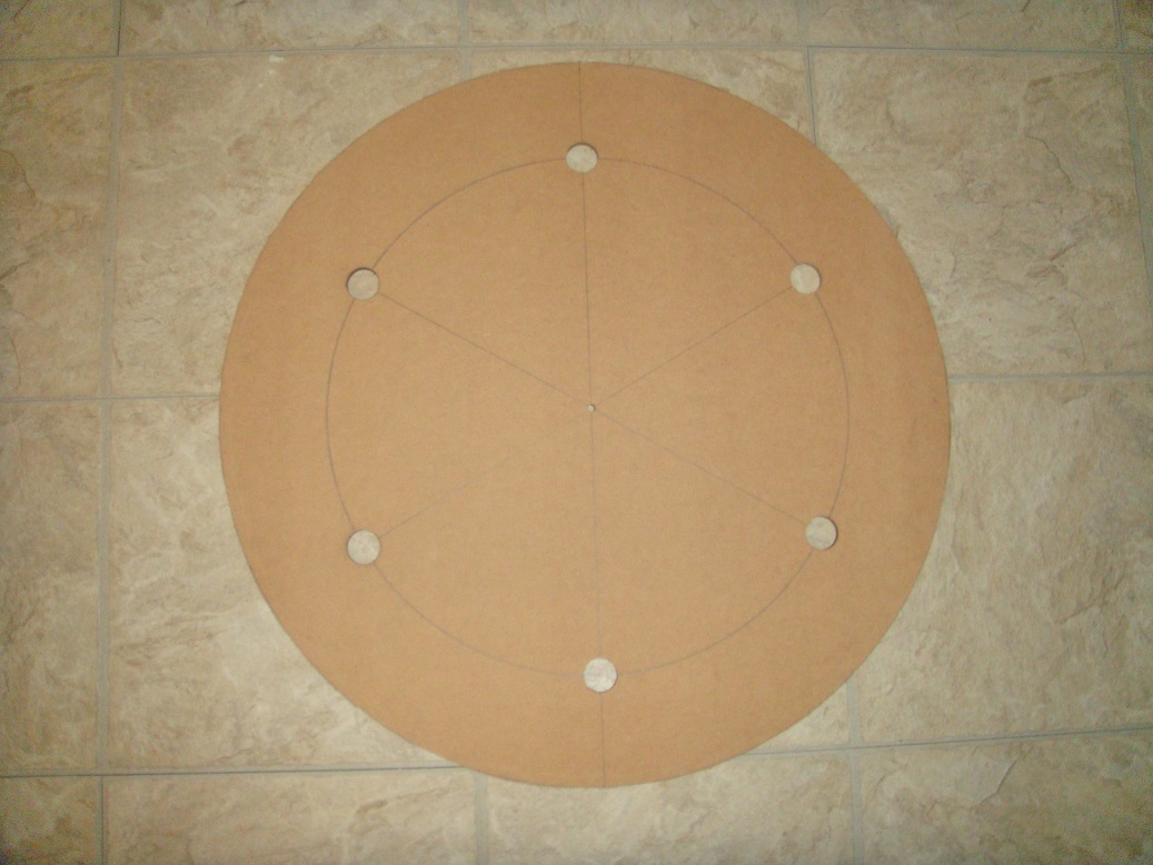
I was able to cut out my larger 24 inch wheels, and to bore the 27 millimeter holes in them. Here's a view of one of the wheels. The holes are centered on a 17 inch circle (8.5 inch radius) at a point where each of six 60 degree radian lines intersect that circle. The hole at the center of the wheel is drilled 1/4 inch to accept a 1/4 inch x 2 inch long stove bolt that is fitted with a 1/4 inch washer on each side of the wheel and then snugged with a 1/4 inch nut. This way I can mount the stove bolt in a drill chuck to rotate the wheel as I sand the rough cut perimeter, which was cut with a saber saw. After sanding the perimeter, I will enlarge the center hole to 3/8 inch to accept the shaft which the wheels will be rotating upon.
Below is an image of the 27 millimeter boring tool that I used for drilling the pipe attachment bore holes. The pilot drill for this tool is 3/16 inch. While this appeared to be an ideal tool for the intended use, I found that, while cutting, the space between teeth loads up rather quickly and that I have to keep cleaning out that material since it has nowhere to go. Also, I found that even though the hardboard panel is only 1/4 inch thick, it was difficult to drill more than half way through the panel without burning the material. Thus, I found that the best solution was to drill just half way through one side and then flip the panel over to finish drilling from the other side. For a larger size build I would definitely prefer using an adjustable cutting tool.
"Seek wisdom by keeping an open mind to alternative realities, questioning authority, and searching for truth. Only then, when you see or hear something that has 'the ring of truth' to it, will it be as if a veil has been lifted, and suddenly you will begin to hear and see far more clearly than ever before." - Rickoff
Here's a photo showing what I decided to use for the wheel hubs. What you see is a 3/8 inch inside diameter shaft collar having a 3/8 inch width and 3/4 inch outside diameter, fitted with a shaft attachment set screw which you see exposed. The shaft collar is bonded to a 1/8 inch thick, 1 and 1/2 inch diameter fender washer using a clear 5 minute epoxy. Each wheel has two of these hubs sandwiching the wheel center, and are drawn tightly against the wheel by the two #8-32 pan head stainless screws seen in the photo, and fitted with flat washers and nuts on the opposite side. I pre-drilled two of the fender washers with a 5/32 inch drill bit using my bench top drill press, then inserted the 3/8 inch shaft into an undrilled hub assembly, through the center hole of the wheel, and on through the drilled hub assembly. Locking the shaft collars onto the shaft, I then used the pre-drilled holes as a guide to drill through the wheel and the undrilled hub washer. By the way, I had actually only inserted the shaft as far as the tip of the shaft collar before drilling so as to prevent any damage to the shaft from the drill chuck, and then extended the shaft further out before taking the photo. I had originally planned to use only one hub assembly for each wheel, but decided on using two for additional stability. With the two screws passing through each wheel and locking the hubs together, there is absolutely no chance of a wheel breaking loose from a hub, or the two wheels drifting out of proper alignment with each other. I would have preferred using 1/8 x 2 inch fender washers if they had been available, as this would have allowed more space between the screws and the shaft collars, but couldn't find larger ones locally. I also would have preferred using Torx star drive screws rather than these Phillips head screws, but made do with what was available. Two more shaft collars will be used near the outer ends of the shaft to ride against the bronze bushing flanges in order to eliminate any side play. My next step will be to lay out the attachment areas on the wood base, and to attach the 6 anchors, 2 uprights, and 4 stabilizer links.
"Seek wisdom by keeping an open mind to alternative realities, questioning authority, and searching for truth. Only then, when you see or hear something that has 'the ring of truth' to it, will it be as if a veil has been lifted, and suddenly you will begin to hear and see far more clearly than ever before." - Rickoff
Good one, Cadman. I have often wondered if the engineers are really as stupid as they seem to be, or if the car companies tell them to design the vehicles to be a nightmare to work on just so that they can bleed the owners dry on parts and labor charges when they come back for service needs. I worked for many years as a mechanic, and also as an automotive machinist, so have always done all my own work. Now that I'm retired, I still do my own work - and for two reasons: 1. I want to be certain it is done right. 2. There is no way I could afford to pay someone charging $100+ per hour, plus tripling the price of parts, to do the work.
remember the checker cars
built to last forever
and they almost deliver that goal
I am quite sad that they went out of business in the 1970s
but it really does show that people end up getting what they buy
people voted for the cars designed to fall apart with what they bought.
and that is not about to change now
now there are so many regulations on a new car company that they are not really possible.
so past people have really set the future, or at least until this current law set fails to apply
First of all, let me thank you folks for your condolences on the loss of my younger brother. I genuinely appreciate that.
Ramset - good to hear from you, and yes, it would be fun to talk over a cup of coffee some day.
Bro Mikey - As one can see, from the video you posted, the soda bottles on the bike wheel configuration that is so often seen posted on the Internet is simply a hoax, and as this fellow explains at the 10:50 elapsed time mark in this video, his build of Bhaskara's Wheel using curved tubes with mercury also does not work. It simply appears that the wheel immediately starts to spin on its own after the last tube is installed, and of course any truly overbalanced wheel would in fact be a self starter. What he reveals, however, is that he tricks the viewer by giving the hub of the wheel a spin with his hand. Thus, nothing to see here except an explanation as to how people can be easily deceived by believing that they have witnessed something visually, and that it must be factual for that reason when it was only an illusion.
I can promise that whatever the outcome of my build happens to be, there will be no deception or illusions.
"Seek wisdom by keeping an open mind to alternative realities, questioning authority, and searching for truth. Only then, when you see or hear something that has 'the ring of truth' to it, will it be as if a veil has been lifted, and suddenly you will begin to hear and see far more clearly than ever before." - Rickoff
I had a little extra time today to assemble the flanged bushings on the uprights, and mounted shaft collars on the 3/8 inch x 6 inch shaft, leaving 3/8 inch of shaft at each end to be inserted into the bearings. Assembled in this manner, this leaves exactly 4 and 1/2 inches of unoccupied shaft space between the inside surface of the outer shaft collars. It would appear, when looking at the below photo, that the space is about 1/16 inch less than that, but this is because of the angle of viewing. The 4 and 1/2 inch space will be more than enough to accommodate the two 1/4 inch thick wheels and their hubs, spaced 1 inch apart for the pipe end caps clearances, as the overall length of this wheel and hub assembly will be 2 and 1/2 inches.
"Seek wisdom by keeping an open mind to alternative realities, questioning authority, and searching for truth. Only then, when you see or hear something that has 'the ring of truth' to it, will it be as if a veil has been lifted, and suddenly you will begin to hear and see far more clearly than ever before." - Rickoff
The remaining question to be resolved is whether or not the 3/8 x 6 inch shaft will be long enough to allow adequate space between the uprights so that the pipes, when assembled to the wheels, will not run into any interference from the uprights when the wheels are turning. Since the wheels are 1/4 inch thick, and there is an intervening space of 1 inch between the two wheels, the dimension between the outer surface of the wheels will be 1 and 1/2 inches. At those outer surfaces, there will be a 90 degree pipe elbow extending an additional 2 inches, and thus the overall width to be concerned with will be 1.5 + 2.0 + 2.0 = 5.5 inches. As can be seen from the photo below, the actual clearance is 6.375 inches, or 6 and 3/8, so there is more than enough space. In fact this will leave a 7/16 inch clearance between the pipe elbows and the uprights at each end of the assembly.
Knowing the spacing between the uprights is 6.375 inches, the wood base can now be laid out for the placement of the feet that will be attached to the bottom end of the uprights, and the 4 anchors that will be used to connect stabilizer links between the anchor points and the uprights. I'll show the layout lines, with upright feet and anchors attached to the base, in my next post.
Thanks for your continued interest in this project.
"Seek wisdom by keeping an open mind to alternative realities, questioning authority, and searching for truth. Only then, when you see or hear something that has 'the ring of truth' to it, will it be as if a veil has been lifted, and suddenly you will begin to hear and see far more clearly than ever before." - Rickoff
Mickey:
Can we not clutter up this build with this obviously fake garbage. Rick is a very talented and precise builder and what you posted has nothing to do with "his" build. It only side tracks on where the direction of intent should be kept.
Mickey:
Can we not clutter up this build with this obviously fake garbage. Rick is a very talented and precise builder and what you posted has nothing to do with "his" build. It only side tracks on where the direction of intent should be kept.
thay
Just because someone disagrees with you does NOT make them your enemy. We can disagree without attacking someone.
I just realized that none of my pictures are showing. Sorry about that. It happens whenever my 50 Megabyte daily bandwidth allotment at the storage site (keepandshare.com) is exceeded, and this often happens after I post a new photo. So, if you don't see a photo that I mention, try returning either after midnight (Eastern US Standard time) or come back a day or two later. I didn't realize my photos weren't appearing until I attempted to show a new photo this evening. I'll try and upload that photo to my Microsoft OneDrive for my next post.
"Seek wisdom by keeping an open mind to alternative realities, questioning authority, and searching for truth. Only then, when you see or hear something that has 'the ring of truth' to it, will it be as if a veil has been lifted, and suddenly you will begin to hear and see far more clearly than ever before." - Rickoff
I was able to lay out the birch plywood stock that I am using for the supporting base, and attached the two feet that the uprights will be fastened to, as well as the four anchor points which will be connected to the uprights by stabilizer links. I added measurements, after capturing the image, for reference by anyone interested in the build. Note that the 5/16 inch measurement is half the width of an upright, which is 5/8 inch wide. The two anchors 8 inches from the uprights will be connected at the mid height of each upright, where a hole already exists. The two anchors at the outer edges of the base's center line will be connected to the right side of the uprights at a lower point. It will appear, when looking at the photo, that the outer edges of the base board are somewhat curved, but they are not - it is an effect caused by the camera lens.
I used #6 x 3/4 inch sheet metal screws (0.163 inch diameter) to attach the feet and anchors to the base, and pre-drilled the screw holes using a 7/64 inch drill bit (0.107 inch). As you can see, the base is 12.6875 inches wide, and the reason for this was because, when cutting from what I had remaining of the birch plywood, this was the maximum allowable. I would actually have preferred a 16 inch width, but figured I'd make do with what I had on hand. Each anchor has two mounting holes for attachment to the stabilizer links, so even the shorter links should provide good stability. The reason why I am only anchoring at one side of the apparatus is mainly because I wanted to leave the left side view unobstructed by any stabilizer links. I feel that the current support apparatus, with stabilization triangulated for each upright, will be more than adequate. After all, if this works as imagined, the wheels will be turning slowly, and the amount of water being used in this build will not produce much of a sloshing effect.
"Seek wisdom by keeping an open mind to alternative realities, questioning authority, and searching for truth. Only then, when you see or hear something that has 'the ring of truth' to it, will it be as if a veil has been lifted, and suddenly you will begin to hear and see far more clearly than ever before." - Rickoff
 Tweet
Tweet


Comment