Announcement

Collapse
No announcement yet.

Magnetic field of a bifilar pancake coil

Collapse
X
 
  • Filter
  • Time
  • Show
Clear All
new posts

  • #31
    Originally posted by ET-Power View Post
    That single cable and ground to the pancake coil in the dielectric video and LEDs was truly something SPECIAL!

    Great Work Man!

    Thanks,
    yeah who doesn't like flashing lights?

    I like your enthusiasm


    the top and bottom coils, need to resonate at the same frequency, so they become part of the same field. I adjust the resonant frequency, by putting a variable capacitor parallel to one of the coils (the coil with the higher resonant frequency). This added capacitance, lowers the resonant frequency.

    To be clear about the capacitor, the windings, are the plates.
    To get more gain, would mean raising the voltage, by using larger voltage pulses.

    More gain, is not only due to voltage, but also to the plate area, and the closeness of the plates. The plates, are the windings. So, if you would use flat wires, or foil, as a winding, and if you make shure the windings are really close. it would give a better gain.

    I found, the smaller the better. I've build some coils with 0,75mm2 Speaker wire. But its not ideal. I've also made a coil out of aluminum foil, and plastic flower wrapping foil. (that was a hell of a job!) that worked good. but then you have the problem of how to put the coil into resonance (or how to put 2 coils in resonance around another coil). Not very practical.

    Another gain factor, is the dielectric medium between the windings. As in a capacitor it works best, when a dielectric material is between the plates. You could use glue, or candle wax.

    For me it was glue (cyanoacrylaat). But it was just to fixate the windings.

    So, plate area, voltage, distance between the windings, dielectric material.

    I tried to make the coils as equal as possible. but they weren't perfect. And Tuning, is a dynamic thing. It depends on the setup. there is also capacitance between the bifilar coils. I have a osciloscoop to see the signal, and the voltage rise. but you could use neon bulbs (those small ones) as they light brightly up, when connected to a coil in resonance (yes single wire again).
    Last edited by evostars; 04-09-2017, 11:49 PM.

    Comment


    • #32
      Originally posted by Sputins View Post
      It is funny that while Tesla invented the Bifilar coil, it seems that he hasn’t really specified on where, how or for what application it is really intended for except to say as per the patent, “Coil for Electromagnets”. So that leaves it open for broad speculation.
      Indeed.
      And, I wouldn't know why to use a bifilar pancake coil as an electromagnet...
      It seems its more like a transformer. Transforming short current pulses, into magneto dielectric longitudinal waves
      Last edited by evostars; 04-10-2017, 12:06 AM.

      Comment


      • #33
        Pancake electro magnet.

        Originally posted by evostars View Post
        Indeed.
        And, I wouldn't know why to use a bifilar pancake coil as an electromagnet...
        It seems its more like a transformer. Transforming short current pulses, into magneto dielectric longitudinal waves
        Tesla sold that patent to Westinghouse, and Westinghouse manufactured the "Scrapyard Magnet". The large gauge pancake coil sat over a ferrite disk, and was magnetized by a pulse from a large capacitor. The coil was reverse pulsed and the scrap dropped. The magnet was powered by a 6 volt lead acid battery, and picked tons of metal up for practically nothing. The other kind of electro-magnet would need to plug into a wall outlet and would run a large electric bill up.
        Last edited by Allen Burgess; 04-10-2017, 12:51 AM.

        Comment


        • #34
          Originally posted by Allen Burgess View Post
          Tesla sold that patent to Westinghouse, and Westinghouse manufactured the "Scrapyard Magnet". The large gauge pancake coil sat over a ferrite disk, and was magnetized by a pulse from a large capacitor. The coil was reverse pulsed and the scrap dropped. The magnet was powered by a 6 volt lead acid battery, and picked tons of metal up for practically nothing. The other kind of electro-magnet would need to plug into a wall outlet and would run a large electric bill up.
          interesting indeed, thanks for sharing.
          now i see the resemblance with your hexnut experiment. do they let go if you pulse them with a reverse current?

          to make the scrapyard magnet work, there should be a ferrite disk above, around and inside the center of the coil. the scrap metal would close the magnetic loop. (like the hexnuts surrounds the pulsed wire).

          Comment


          • #35
            Originally posted by evostars View Post
            interesting indeed, thanks for sharing.
            now i see the resemblance with your hexnut experiment. do they let go if you pulse them with a reverse current?

            to make the scrapyard magnet work, there should be a ferrite disk above, around and inside the center of the coil. the scrap metal would close the magnetic loop. (like the hexnuts surrounds the pulsed wire).
            @evostars,

            Yes, a reverse pulse will unlock the Hex nuts. Have a look at this video by Robert Murray-Smith if you haven't already seen it:

            https://www.youtube.com/watch?v=MZzosuvfvE4

            The bifilar and single wire double strength test with the iron nail core needs to be done like this: First, the bifilar needs a preliminary "Ring Pulse" to shock the coil into resonance which cancels the self inductance; Then, a second locking pulse will penetrate the ferrite core with no magnetic field interference and act as the single wire does, except focused to the center.

            Shocking the single wire coil results in a storage of power in the coil windings as a magnetic field, and this field blocks any further pulse from reaching the ferrite core.
            Last edited by Allen Burgess; 04-10-2017, 11:58 AM.

            Comment


            • #36
              As I said raising the voltage would raise the gain.
              I have tested this. Untill now i used a 11,68Vdc powersupply to pulse the center coil. and as a result I got 950Vdc in my capacitors, within 2 seconds.

              The enenrgy stored in a capacitor is related to the square of the voltage.

              I now used a 19Vdc 4,5A labtop powersupply. and with the same setup, the voltage went to 1500Vdc. my meter has a rating of 1000V but it worked fine, but it might be off.

              the input voltage goes up with 62% but the output energy is up with 150%.
              I have to do more measurements (input current change) So I cant make conclusions.

              But its clear a raise in the pulse voltage results in a lot more energy in the capacitors.

              Very interesting and inspiring.

              Comment


              • #37
                Originally posted by evostars View Post
                Thanks,
                yeah who doesn't like flashing lights?

                I like your enthusiasm


                the top and bottom coils, need to resonate at the same frequency, so they become part of the same field. I adjust the resonant frequency, by putting a variable capacitor parallel to one of the coils (the coil with the higher resonant frequency). This added capacitance, lowers the resonant frequency.

                To be clear about the capacitor, the windings, are the plates.
                To get more gain, would mean raising the voltage, by using larger voltage pulses.

                More gain, is not only due to voltage, but also to the plate area, and the closeness of the plates. The plates, are the windings. So, if you would use flat wires, or foil, as a winding, and if you make shure the windings are really close. it would give a better gain.

                I found, the smaller the better. I've build some coils with 0,75mm2 Speaker wire. But its not ideal. I've also made a coil out of aluminum foil, and plastic flower wrapping foil. (that was a hell of a job!) that worked good. but then you have the problem of how to put the coil into resonance (or how to put 2 coils in resonance around another coil). Not very practical.

                Another gain factor, is the dielectric medium between the windings. As in a capacitor it works best, when a dielectric material is between the plates. You could use glue, or candle wax.

                For me it was glue (cyanoacrylaat). But it was just to fixate the windings.

                So, plate area, voltage, distance between the windings, dielectric material.

                I tried to make the coils as equal as possible. but they weren't perfect. And Tuning, is a dynamic thing. It depends on the setup. there is also capacitance between the bifilar coils. I have a osciloscoop to see the signal, and the voltage rise. but you could use neon bulbs (those small ones) as they light brightly up, when connected to a coil in resonance (yes single wire again).
                Thank you for the clarity and information shared!

                I have yet to be able to tune coils/tank circuits into resonance because I do not have a function generator or frequency counter.

                I attempt to tune them as best as possible by playing around with varying capacitance first in mF, then μF, then nF, and then in pF. It's definitely not the best, I look forward to getting the fancy tools soon so I can actually dial it in much more accurately and in much less time.
                "Rebellion to tyrants is obedience to God." - Benjamin Franklin + Thomas Jefferson

                Comment


                • #38
                  Originally posted by Allen Burgess View Post
                  Tesla sold that patent to Westinghouse, and Westinghouse manufactured the "Scrapyard Magnet". The large gauge pancake coil sat over a ferrite disk, and was magnetized by a pulse from a large capacitor. The coil was reverse pulsed and the scrap dropped. The magnet was powered by a 6 volt lead acid battery, and picked tons of metal up for practically nothing. The other kind of electro-magnet would need to plug into a wall outlet and would run a large electric bill up.
                  Thanks for this, didn't know about him selling to Westinghouse and them using them in scrapyard EM's.

                  Thanks!
                  "Rebellion to tyrants is obedience to God." - Benjamin Franklin + Thomas Jefferson

                  Comment


                  • #39
                    Originally posted by evostars View Post
                    As I said raising the voltage would raise the gain.
                    I have tested this. Untill now i used a 11,68Vdc powersupply to pulse the center coil. and as a result I got 950Vdc in my capacitors, within 2 seconds.

                    The enenrgy stored in a capacitor is related to the square of the voltage.

                    I now used a 19Vdc 4,5A labtop powersupply. and with the same setup, the voltage went to 1500Vdc. my meter has a rating of 1000V but it worked fine, but it might be off.

                    the input voltage goes up with 62% but the output energy is up with 150%.
                    I have to do more measurements (input current change) So I cant make conclusions.

                    But its clear a raise in the pulse voltage results in a lot more energy in the capacitors.

                    Very interesting and inspiring.
                    STELLAR ! ! ! !
                    "Rebellion to tyrants is obedience to God." - Benjamin Franklin + Thomas Jefferson

                    Comment


                    • #40
                      Originally posted by ET-Power View Post
                      Thank you for the clarity and information shared!

                      I have yet to be able to tune coils/tank circuits into resonance because I do not have a function generator or frequency counter.

                      I attempt to tune them as best as possible by playing around with varying capacitance first in mF, then μF, then nF, and then in pF. It's definitely not the best, I look forward to getting the fancy tools soon so I can actually dial it in much more accurately and in much less time.
                      Remember, the most fancy tool you need, is your mind. You can find the rest of the tools cheap, if you look around. alibaba.com can provide a lot. like the function generator i use. And ask around, if anybody has an old working osciloscope, they are cheap, but they do the trick. As long as you can see what the signal is doing, you can learn a lot from it. It doesnt need to be expensive or new, as long as it provides your brain with information.

                      Old (AM) radios have variable capacitors in them, they are very handy with tuning. The bifilar coils you see in my video's are tuned with around 250pF depending on the setup...

                      A gibson les paul, and a Marshall amplifier, do not create great music. Its the artists heart and mind.

                      Comment


                      • #41
                        Oliver Nichelson

                        Back in 2006 at the ExtraOrdinary Science Conference, Oliver Nichelson presented on the topic of Tesla's fuel-less Generator.


                        While I have no real comments concerning the fuel-less generator, during Oliver’s 2006 presentation he covers the Tesla Bifilar* Coil, and shares some of his findings.

                        Because of the self-capacity of the bifilar coil, for the same diameter coil (or form factor) the self-resonant frequency of the bifilar is about half that of the single wound coil. So the chat here shows the RO of the single wound coil being 3.5Mhz and the bifilar coil 1.5Mhz.


                        The most interesting aspect is the voltage gain… The voltage gain of the bifilar coil is about nine (9) times that of the single wound coil. Oliver says for a single layer coil, the voltage gain is always about nine times as much (900%), no matter the form factor. (Flat spiral or tubular form)


                        Of course back in the day, capacitors were called condensers because it was believed that they condense the Aether. - So Oliver calls the bifilar coil an “Active Condenser”

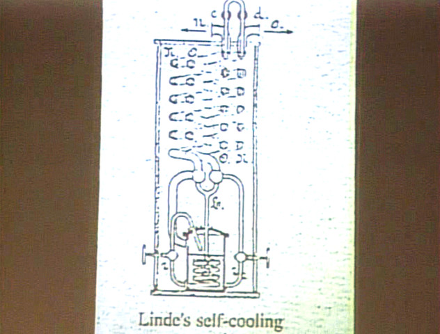
                        Carl Linde came with a Bifilar Coiled, self-cooling device…


                        *(When I type Bifilar, I also mean series connected, the end of the first winding is connected the beginning of the second).

                        So I’ll insert the screen shots later tonight, for now here is a .pdf of Oliver’s work, which contains some info on the Bifilar coil…

                        http://energythic.com/usercontent/3/....Nicholson.pdf

                        Sputins
                        Last edited by Sputins; 04-11-2017, 09:45 AM.
                        "Doesn't matter how many times you kick the coyote in the head, it's still gonna eat chickens". - EPD

                        Comment


                        • #42
                          Originally posted by Sputins View Post

                          Oliver Nichelson

                          The most interesting aspect is the voltage gain… The voltage gain of the bifilar coil is about nine (9) times that of the single wound coil. Oliver says for a single layer coil, the voltage gain is always about nine times as much (900%), no matter the form factor. (Flat spiral or tubular form)

                          Of course back in the day..........................

                          Sputins

                          Back in the day did he have a proof of concept device that we can
                          point to? Or is this PDF a proof? It is nice to hear that the coil can do so
                          many things but is there any experiment that we can do to learn from?

                          Hearsay is something to start with, then we must back up the idea
                          with some sort of hands on testing. Bifilar coils are many things it seems.

                          Maybe even a refrigerator? Can you compress what you have gathered
                          from these ideas into a reasonable statement? Thx Sput

                          Comment


                          • #43

                            So I’ll insert the screen shots later tonight, for now here is a .pdf of Oliver’s work, which contains some info on the Bifilar coil…

                            http://energythic.com/usercontent/3/....Nicholson.pdf

                            Sputins
                            interesting document. thanks for sharing.

                            Comment


                            • #44
                              Originally posted by BroMikey View Post

                              Back in the day did he have a proof of concept device that we can
                              point to? Or is this PDF a proof? It is nice to hear that the coil can do so
                              many things but is there any experiment that we can do to learn from?

                              Hearsay is something to start with, then we must back up the idea
                              with some sort of hands on testing. Bifilar coils are many things it seems.

                              Maybe even a refrigerator? Can you compress what you have gathered
                              from these ideas into a reasonable statement? Thx Sput

                              Hi Brother Michael & all.

                              I'm not sure of any proof of concept device that one can point to, except there maybe some hints in that pdf document?

                              As for testing and experiments with or of the bifilar coil, I think there are still many aspects to learn and to know for sure... I noticed that on the other forum, they can't even agree on the inductance of a bifilar coil V's a single wire wound coil. So doing one's own tests and charts is where the most learning and truth will come from. There are different ways of connecting to two wires as well. .

                              Given that the TBC produces a much higher voltage gain than a standard coil, we can safely assume the device has its capacity in series with its inductance, to produce a series resonant circuit, since its voltage is at a maximum.

                              It has been said that there is nothing special about the Tesla Bifilar Coil! Because of its simple elegance in how it is conducted, where it becomes a coils and a capacitors all in one, is actually something pretty marvelous, this from the mind of Tesla.

                              Is the Tesla Bifiar coil an OU device? No, not of itself, but it may certainly be a component of an OU device or system, IMO.

                              Stanley Meyer used stainless steel, bifilar wound chokes in his system & also Floyd Sweet made use of them, I believe.

                              I'm doing some of my own basic tests & experiments myself with this.

                              I'll say this though, which I haven't seen any results from experiments on as yet (they may already exist somewhere)? But here are two thoughts on applications for the TBC.

                              1, I would like to see a bifilar coil run as a quarter wave resonant coil, like a standard Tesla Secondary Coil, but analyse the displacement current that's produced from the neutral terminal. As we see a higher voltage resonant rise than a standard coil, it might produce a more pronounced displacement current, as the displacement current is derived from a the rate of change in the dielectric field with and more so with a sharp high voltage gradient. - But it's resonant frequency occurs at a lower frequency than normal, so some loss might be expected which may counter act the HV advantage? (I'll have a crack at this myself soon).

                              2, With the coils being connected from the end of the first winding, connected to the beginning of the second which gives rise to the additional capacity and likely a change in inductance... If we then connect them back in parallel again, we are back to two parallel coils (lower L) and a lower capacity (C). So if we have a very fast connection and re-connection between the two states of connection, this would give rise to parametric change, of both inductance and capacitance changing at the same time, with respect to time, which might have unique properties for experiments with OU outcomes... (But there are at least two fundamental resonant frequencies here)!

                              Just some thoughts here only, it may not pan out that way!

                              Sputins
                              "Doesn't matter how many times you kick the coyote in the head, it's still gonna eat chickens". - EPD

                              Comment


                              • #45
                                Originally posted by Sputins View Post
                                Hi Brother Michael & all.

                                I'm not sure of any proof of concept device that one can point to, except there maybe some hints in that pdf document?

                                As for testing and experiments with or of the bifilar coil, I think there are still many aspects to learn and to know for sure... I noticed that on the other forum, they can't even agree on the inductance of a bifilar coil V's a single wire wound coil. So doing one's own tests and charts is where the most learning and truth will come from. There are different ways of connecting to two wires as well. .

                                Given that the TBC produces a much higher voltage gain than a standard coil, we can safely assume the device has its capacity in series with its inductance, to produce a series resonant circuit, since its voltage is at a maximum.

                                It has been said that there is nothing special about the Tesla Bifilar Coil! Because of its simple elegance in how it is conducted, where it becomes a coils and a capacitors all in one, is actually something pretty marvelous, this from the mind of Tesla.

                                Is the Tesla Bifiar coil an OU device? No, not of itself, but it may certainly be a component of an OU device or system, IMO.

                                Stanley Meyer used stainless steel, bifilar wound chokes in his system & also Floyd Sweet made use of them, I believe.

                                I'm doing some of my own basic tests & experiments myself with this.

                                I'll say this though, which I haven't seen any results from experiments on as yet (they may already exist somewhere)? But here are two thoughts on applications for the TBC.

                                1, I would like to see a bifilar coil run as a quarter wave resonant coil, like a standard Tesla Secondary Coil, but analyse the displacement current that's produced from the neutral terminal. As we see a higher voltage resonant rise than a standard coil, it might produce a more pronounced displacement current, as the displacement current is derived from a the rate of change in the dielectric field with and more so with a sharp high voltage gradient. - But it's resonant frequency occurs at a lower frequency than normal, so some loss might be expected which may counter act the HV advantage? (I'll have a crack at this myself soon).

                                2, With the coils being connected from the end of the first winding, connected to the beginning of the second which gives rise to the additional capacity and likely a change in inductance... If we then connect them back in parallel again, we are back to two parallel coils (lower L) and a lower capacity (C). So if we have a very fast connection and re-connection between the two states of connection, this would give rise to parametric change, of both inductance and capacitance changing at the same time, with respect to time, which might have unique properties for experiments with OU outcomes... (But there are at least two fundamental resonant frequencies here)!

                                Just some thoughts here only, it may not pan out that way!

                                Sputins
                                Yes! doing your own research gives the best insights.

                                For your point 2, I wondered about that. With a simple switch in the connection, you can cancel the magnetic field. If this is used in a bedini type setup, then you can pulse it, create a magnetic field, push/pull a magnet. then when the action becomes unwanted (magnet passes over) you can switch the setup, and cancel the field of the coil. But I never tried this. It sure looks like what bedini's setup is all about. switching the bifilar coil.

                                Myself, im not interested in moving magnets. I'm more interested in non moving solid state.

                                The bifilar coil at its resonant frequency produces a dynamic field.

                                I just did a test, and blew a uf4007 (1A 1000V) diode. It was in the 1500Vdc setup. I was connecting my meter, to the diodes, when it exploded.
                                Attached Files

                                Comment

                                Working...
                                X