Announcement

Collapse
No announcement yet.

Splitting The Positive

Collapse
X
 
  • Filter
  • Time
  • Show
Clear All
new posts

  • #31
    Also beware that China Man speak bad English sometimes
    he calls this a BUCK CONVERTER but I don't think so.

    It looks like a simple circuit? But i don't know.

    Chip number XL4016


    http://www.ebay.com/itm/8A-DC4-40V-
    To-DC2-36V-Buck-Power-Converter-200W-XL4016-
    PWM-Volt-Step-Down-Moudle-/262159873990?hash=item3d09f237c6:g:FgkAAOS
    wHQ9WVYQj


    Description
    Main parameters:

    Product name: DC voltage converter
    Conversion method: PWM
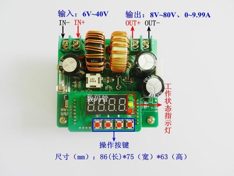
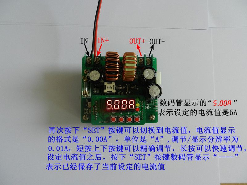
    Input voltage: DC 4-40V
    Output voltage: DC 1.25-36V
    Max current: 8A
    Max power: 200W
    Conversion efficiency: 94%
    Switch frequency: 180KHz
    Appearance size: 61*41*27mm

    Features:

    This product uses XL4016 switch voltage conversion chip, and
    realizes double rectification by collaborating with MBR10200.
    Max input can reach 40V, continuously adjustable
    for 1.25~36V output.

    Max output current can reach 8A.
    Need a fan.
    Recommend no more than 5A for long-time work.
    Support panel installation:
    1. Drill a hole for 7mm on the panel.
    2. Extend potentiometer handle.
    3. Tighten the screw and cover the knob.

    Package List:

    1 x 200W XH-M401 DC-DC 4-40V To 1.25-36V Buck Module 8A XL4016E1 Voltage Converter
    Last edited by BroMikey; 06-11-2016, 11:27 PM.

    Comment


    • #32
      LTC3780 Constant voltage and current


      http://www.ebay.com/itm/DC-to-DC-
      converter-Boost-buck-power-supply-Constant-voltage-
      current-Regulators/351755769339?hash=item51e647
      15fb:g:RRsAAOSwqv9V6Mrz


      LTC3780 Constant voltage and current DC to DC converter 4-32V to 0.8-32V adjustable Automatic Step-up/step-down Boost/buck power supply Module Solar Wind Energy charging Vehicle Voltage Regulator led driver #1300201

      Module parameters:

      Module name: 8A Automatic Step-up/step-down Constant voltage and current module

      Module Properties: non-isolated synchronous rectifier Automatic Step-up/step-down module

      Input voltage: DC 4-32V

      Input Current: 8A (MAX),Peak 10A(Long natural Radiating Working within 6A)

      Quiescent Current: 5mA (working voltage not simultaneously be errors)

      Output voltage: DC 0.8-32V continuously adjustable

      Output Current: 8A (MAX) Peak 10A (<=6A long natural cooling inside)

      Constant current output range:0.2-8A

      Operating temperature: -40 to +85 ° C

      Operating Frequency: 200KHz

      Conversion efficiency: Up to 98% (Efficiency is related to Input
      and output voltage, current, voltage difference)

      Over current protection: yes

      Short circuit protection: (input 10A fuse) Double circuit
      protection, use more secure

      Over-temperature protection: Yes (over-temperature
      automatically reduces the output voltage)

      input Reverse Polarity Protection: None, (if required in the input string into the diode)


      Installation: 4pcs 3mm screws

      Output preventanti-irrigation: None, when used for charging
      coupled blocking diode, otherwise it will damage the module.

      Wiring: none welding wire terminal output,
      (IN as input, OUT is the output)

      Module dimensions: length 60mm X width 51mm X height 20mm

      PACKING INCLUDING:

      1x power supply Module

      Comment


      • #33
        For Your Info (FYI) This is what I found out about the scooter motor
        commutator design for clamping the winding into it. I am afraid to
        press it back down but I only raised each tab 2mm or less. Still
        I might solder the wire on instead.


        Comment


        • #34
          Boost Converter 10AMP 400Watts

          It's gonna Bee Sweet. Sposta bee here in 2 weeks


          Specification:

          Input voltage : 6V-40V

          Input Current: 15A(max)

          Output voltage : 8V-80V(adjustable)

          Output power:400W(max)

          Output current: maximum output current of 10A ( adjustable )

          Output power: the effective power P = input voltage V * 10A

          Conversion efficiency: up to 95% ( input voltage, current;
          output voltage and current impact of conversion efficiency )

          Short circuit protection : Fuse
          Last edited by BroMikey; 06-16-2016, 04:19 AM.

          Comment


          • #35
            Originally posted by Turion
            You wil have to let us know if it will work wired as Matt has shown us. Some of the better boost converters I have purchased will NOT run that way. I have purchased 8 different boost converters and two of them would not run the way Matt showed us to wire them. Unfortunately, they were the more efficient ones.

            Dave
            I sure will and I also remembered that when I bought it, I
            would like a boost that is a tiny bigger than 100 watts so
            I decided to take the chance. I can always buy more.

            I used 20awg wire and uses 30 extra turns hoping to run
            a tiny bit more power to charge my 2000 ah 12 battery set.

            I would love to charge those big batteries off this small
            Pulse Motor Tesla switch rewound Kool charger.
            Tell Matt I appreciate all the hard work handed over on a
            silver platter, I understand now that the motor switch
            is an off shoot and people don't realize how hard it is to
            duplicate the motor switch action with a circuit.

            When I get it running I'll post my success story for all to see.

            I don't know why I never picked this experiment up? I see it
            so clear now but 2 years ago? I don't know.

            Keep splitting the pos.... everytime you want to run a load
            Humm... I am thinking about it. I am charging batteries.

            I will do what I said first, run a light bulb on pure lectric current
            and watch the battery burn down. Record time and joules.

            A car light bulb as a load is a great way to start because a bulb
            will stay at the same amp draw all the way down to 12V + 12V
            =24v to stop at. Bulbs are nice to work with, you can measure
            the current once or twice say at the end and the draw will be the
            same.

            I will use all three batteries in parallel to run my light till the three
            12volt batteries reach 12v or maybe 11.5v something like this.

            I don't need my magic switching motor to do that nor a converter
            yet this must be done to give me an idea how many joules my
            batteries under test can hold and how many joules is consume in
            conventional (Burn them amps to the ground) operation.

            With an idea how many joules I have in those three batteries
            I will then connect all three batteries up to the light bulb as
            suggested with a split pos....... arrangement.

            That I can tell you will far surpass the previous connection.

            I see all of the information, the diagrams, connection paths.

            The part that is making my brain go cross-eyed is how a load
            with a voltage drop doesn't cost anything in joules to run.

            And I know the answer too. The answer is that instead of power
            going to ground and burning up it is going to another battery to
            charge it. My conventional horns are sticking out all
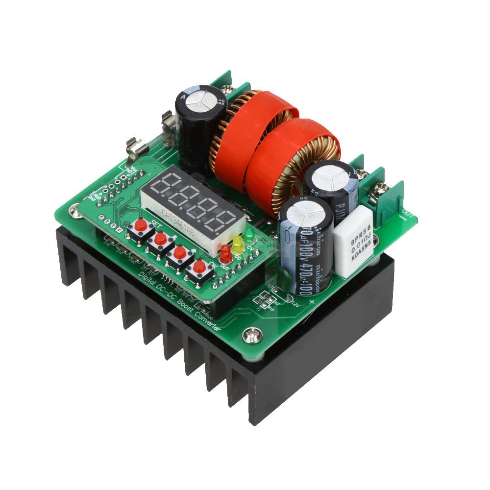
            over.


            $18

            Last edited by BroMikey; 06-17-2016, 02:05 AM.

            Comment


            • #36
              Originally posted by Turion
              Post 969 In the Basic Free Energy Device thread has a link to the pdf of building the motor as well as a link to the schematic of the boost converter.
              ... if you know what dropbox is and have an account:
              http://www.energeticforum.com/renewa...device-33.html
              Last edited by wrtner; 06-17-2016, 03:40 PM.

              Comment


              • #37
                For beginners who have many questions look here
                this video tells you about boost converters.

                Longer wires or longer coils produce higher voltages.


                Working in 105 degree temps is kicking my other end.
                Extreme high temp advisory in effect now.

                http://www.energeticforum.com/289423-post1072.html

                [VIDEO]https://www.youtube.com/watch?v=FRG01YOEQGY[/VIDEO]

                [VIDEO]https://www.youtube.com/watch?v=iI47ZSRxVro[/VIDEO]


                Last edited by BroMikey; 06-18-2016, 02:52 AM.

                Comment


                • #38
                  Okay I did my very first ever SPLIT THE POSITIVE runs
                  And I have to say "IT WORKS!!! Or I am loosing my
                  marbles?

                  Here is what happened. I couldn't wait any longer so I
                  pulled out some of my 2ah Lithium ION (Choice Batteries)
                  Batteries and this diagram shows you how I did it.

                  I ran the system 4 times and each time the current draw on
                  the modified household LED light bulb was always 400 mil-amp
                  at 3.15 volts.

                  These batteries are A-number one charged. All batteries started
                  at 3.85 well one was 3.90 volts. Now after running my load 4 times
                  for 10 minutes and the last time 15 minutes before switching I
                  am reading all batteries higher than the start so there must be
                  some kind of a mistake. I had to say that because it really
                  does seem to work. I'll keep doing it to see where I messed up.

                  I have this crazy feeling as I watch these batteries run this
                  light with no drop in battery capacity. Something is not right.

                  I am pretty tickled about it. Of course in the back of my mind
                  it can't work so I must of made a mistake right?This is to
                  easy. I don't want to start dancing to soon but it really look like
                  we have our foot in the door here.

                  I'll shake these meters to see if they are acting up. Nope no
                  rattle there.

                  I am liking this recirculated power. It is a regular LED bulb from
                  China with the aluminum heat sink and it lights the whole room
                  up. I didn't want to much pull on these little batteries so I only
                  enabled 4 LED's to match the power draw I was after.


                  PS I am back after letting batteries sit for 30 minutes
                  and a final 5th run trying to get these batteries to drop.
                  Battery Bank A = 7.87 v and Battery Bank B = 3.93 v

                  PS the is the second return, I see the loaded voltages now
                  changing first run 7.35 v and 4.05v now after 6 runs the
                  first bank loaded voltage is 7.25v so now miliamp draw
                  went down to 300 ma from the original 400 ma.draw.

                  So little by little the batteries are dropping slightly. I will hook
                  it direct now.


                  Last edited by BroMikey; 06-18-2016, 10:20 AM.

                  Comment


                  • #39
                    Last night I kind of jumped the gun so to speak getting
                    ahead of myself so here it is, the conventional curve (No Curve Yet)
                    that is needed to establish a norm with these batteries.

                    To maintain the 400ma draw I have installed a 1.5 ohm
                    resistor as shown. Let us see what these batteries can
                    do over a period of say an hour or two, then we will
                    split up the same three batteries to run off positive terminals
                    only.

                    Just like the regenx, everybody throws a coil on a magnet
                    wheel and speculates but what about the measurement during
                    transition? I mean some sort of establish norm must set the
                    precedent.


                    It was fun to watch the light run and battery charge the other way.

                    Last edited by BroMikey; 06-18-2016, 09:50 PM.

                    Comment


                    • #40
                      Calculations in Joules

                      Without a precedent of conventional operation this deduction
                      as to whether or not power is being recycled leaves us guessing.

                      If anyone has done this comparison and has it posted online
                      please let me see your results. The calculation is done with grade
                      school math using times tables to multiply volts X Amps per
                      second or Volts X Amps X seconds = JOULES

                      So many Joules per run. Each minute has 60 second so the value
                      of the number 60 is multiplied by your watts. This is watt/minutes

                      So if you are making a run like me at 400ma and 3.15volt for ten
                      minutes your calculation will look like this.

                      .400ma X 3.15volts X (TIME IN SECONDS)

                      Time in seconds for 10 minutes = 60 sec X 10 Min = 600 sec

                      So this means for my experiment

                      (.400ma X 3.15volt = 1.26watts) X 600 sec = 756 Joules

                      Now I can clearly see how many nuggets I ate up over
                      a 10 minute run time. Next looking at battery curves.

                      As a battery runs down it will hold steady at one place for
                      extended periods not moving many points on the scale then
                      all at once it will decline slightly more rapidly and next it will
                      decline very quickly over a short space and fail.

                      I will be back to show you my curve for these batteries.


                      (NOTATION)
                      To be fair conventional runs must be done the same as is required
                      with split positive runs. Split positive runs for my batteries need
                      changing around after 10-15 min. This constitutes a rest interval
                      however small say 2 minutes between runs, therefore each
                      conventional run should follow the same pattern.


                      For those of you who have never seriously considered all of the
                      efforts this man has made to show battery curves I suggest
                      you take advantage of it.

                      God Bless you JOHN B.

                      [VIDEO]https://www.youtube.com/watch?v=4ihOxdKiYmo[/VIDEO]

                      [VIDEO]https://www.youtube.com/watch?v=GYIhZvDDkaU[/VIDEO]
                      Last edited by BroMikey; 06-18-2016, 10:12 PM.

                      Comment


                      • #41
                        Here are a few numbers crunched in for my Lithium ION
                        2ah batteries connected in parallel and conventional mode.

                        I have extended the chart. I will be updating this chart
                        every so many minutes as I collect data.


                        PS notice I have included the amp hour capacity of the
                        batteries at the C20 rate with calculation. Look at the diagram.

                        Later we will need to recalculate what a split positive C20
                        rate would come to to be fair. In the split positive arrangement
                        only 2000mah are considered. A C20 rate for a 2000mah battery
                        comes to a load of 100ma so I would have to run a split positive
                        system 3 times as long to collect data.


                        Last edited by BroMikey; 06-19-2016, 02:29 AM.

                        Comment


                        • #42
                          See the previous chart

                          This chart is bigger so the curve may be seen with
                          greater ease. 270 minutes into the C5 discharge for
                          Lithium ION batteries.

                          The graph has been expanded with a 1 volt area of 3 to 4 volts.
                          Also notice the ever dropping current from over 400ma on
                          start up until now at less than 300ma the run in progress.

                          Last edited by BroMikey; 06-21-2016, 08:31 AM.

                          Comment


                          • #43
                            Joule Count for Chart above

                            As an average over all mili-amp draw from 405ma starting
                            down to 300ma ending a figure of 350ma is found. Yet each
                            segment might be calculated separately each having a specific
                            number of joules and then add them all together.

                            Each time frame for a given ma draw varies.

                            Segment Number

                            (1) 3.90v-3.76v= average =3.83volts X .405 X (sec 900)
                            Joules = 1396 j

                            (2) 3.74v X .400 X 1800sec = 2693 Joules

                            (3) 3.70v X .380 X 2700sec = 3796 Joules

                            (4) 3.67v X .375 X 1800sec = 2477 Joules

                            (5) 3.64v X .360 X 1800sec = 2359 Joules

                            (6) 3.60v X .340 X 1800sec = 2203 Joules

                            (7) 3.56v X .325 X 1800sec = 2083 Joules

                            (8) 3.52v X .305 X 1800sec = 1932 Joules

                            (9) 3.49v X .300 X 1800sec = 1885 Joules

                            10) 3.44v X .280 X 1800sec = 1734 Joules

                            11) 3.33v X .300 X 1800sec = 1798 Joules


                            Total Number of Joules? Nuggets I call them = 22,960 J
                            There is no grey area/kind-a-sorta happy horsezhit this
                            is the number. I will be letting you know. All testing is
                            carried out to the second.
                            Last edited by BroMikey; 06-19-2016, 06:19 AM.

                            Comment


                            • #44
                              These Lithium ION batteries have been charging for an
                              hour now after reconfiguring them into a series string. I use
                              the C5 charge rate, just as I use the C5 discharge rate
                              please make a note of it.

                              Battery voltage must reach 12.6v in the 3 battery series
                              line up with each of the three batteries needing to top
                              out at 4.2v.

                              I bought some impulse relays and am brainstorming a possible
                              switching madness to keep me from changing batteries every
                              30 minute for quite probably days to finish the counter part
                              test to finalize this comparison run.

                              If you have an easy circuit to switch batteries please post
                              here ASAP.

                              Last edited by BroMikey; 06-21-2016, 08:32 AM.

                              Comment


                              • #45
                                Split Positive First Run Under Way.

                                This is where I will stop till the next day as I have no switch gear.
                                For those of you who have not switched batteries
                                every 30 minutes may be over charging the charging
                                battery, and burning up energy as witnessed by no increase
                                in charge voltage when the max charge is reached.

                                This is unacceptable therefore batteries MUST be rotated
                                before energy is thrown away.

                                In the last 2 hours of this first split positive run 2 batteries set
                                at 3.85v and the charge battery at 3.96v

                                The amp draw is closely watched and averaged, the start
                                voltages shown are measure after 30 seconds. Each start up
                                run for 30 minutes is preceded by a 2 minute rest during that
                                time batteries are changed around.

                                I am anxious to continue


                                PS it is day two and I have updated this chart (See Joule Count)

                                We have almost hit the halfway mark for joule counting after 3.5hrs

                                The chart is being updated every so many minutes please
                                stay tuned. It's looking pretty good. I wasted joules I won,t
                                count, not to many. Gotta be sure watt's up with this experiment.
                                I see everyone's post, thank you.


                                SECOND ENTRY DAY TWO

                                It looks like it's going to be on into the night before I reach
                                the 22,000 joules but I can tell you this, the batteries all get a rest
                                and some charging are along the way. I like the way that the
                                battery has time to recover when being charged. To give you
                                an idea of what I mean battery C or the charge battery
                                always stays at 3.95v at 200ma being fed into it.

                                At 300 minutes into this run

                                Battery A = 3.65v
                                Battery B = 3.45v
                                Battery C = 3.95v

                                This is the voltage while the circuit is running and circulating
                                200ma thru my LED light bulb. To keep a C20 rate I should be
                                down to 125ma, instead am going with a C10 rate. Using a
                                C10 rate will cost me joules as compared to the C20 rate
                                yet these Lithium ion batteries are made to handle that.

                                These experiments are more than meets the eye and very
                                little information in video form or otherwise is available on
                                the subject.

                                No one who has the time has taken a systematic approach
                                showing video footage of how energy can be recirculated.


                                Third entry: New graph below, I am running out of space.
                                See 2nd plot below.


                                Last edited by BroMikey; 06-20-2016, 07:50 AM.

                                Comment

                                Working...
                                X